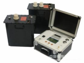
the insulation resistance of electrical equipment or cables. This type of tester is widely used in power systems, industrial production, and scientific research experiments to detect the insulation performance of electrical equipment and ensure safe operation. Below is an article about insulation resistance testers, covering their basic concepts, working principles, application scenarios, and usage precautions.
Overview of Insulation Resistance Tester
Definition and Function
An insulation resistance tester is an instrument used to measure the insulation resistance of electrical equipment or cables. By applying a certain voltage and measuring the resulting current, the insulation resistance can be calculated. Insulation resistance is an important indicator of the insulation performance of electrical equipment; the larger the value, the better the insulation performance.
Importance
In power systems and industrial production, the insulation performance of electrical equipment directly affects the safety and stable operation of the system. Regular testing with an insulation resistance tester can promptly detect defects or aging in insulation materials, prevent equipment failures, and improve the operational efficiency and safety of the power system.
Working Principle
Testing Methods
Insulation resistance testers typically use the following methods to measure insulation resistance:
DC Voltage Method: By applying a certain voltage (usually 50V, 100V, 250V, 500V, 1000V, etc.), the resulting current is measured, and the insulation resistance is calculated.
Automatic Range Selection: Automatically selects the appropriate voltage level based on the insulation resistance of the device under test.
Leakage Current Compensation: Improves measurement accuracy by compensating for the influence of leakage current.
Components
An insulation resistance tester generally consists of the following parts:
Power Module: Provides a stable test voltage.
Measurement Circuit: Used to collect the current signal from the device under test.
Signal Processing Unit: Processes the collected signal and calculates the insulation resistance.
Display and Control Unit: Used to display test results and provide an operation interface for users to adjust test parameters.
Protection Module: Provides overvoltage, overcurrent, and other protection functions to ensure safe operation of the equipment.
Operation Procedure
Preparation Stage: Select an appropriate insulation resistance tester based on test requirements and prepare the equipment to be tested.
Connecting Equipment: Correctly connect the tester to the equipment under test, ensuring reliable connections.
Setting Parameters: Set relevant parameters of the tester, such as test voltage, according to test requirements.
Executing Test: Start the tester to begin measuring insulation resistance.
Reading Results: Read the insulation resistance result from the tester and record it.
Recording Data: Record test data, including insulation resistance, test date, time, environmental conditions, and other information.
Application Scenarios
Insulation resistance testers are widely used in multiple fields:
Power Systems: Used to detect the insulation performance of transformers, cables, motors, and other electrical equipment.
Industrial Production: Used to detect the insulation status of electrical equipment in industrial production, ensuring safe operation.
Scientific Research Experiments: Used in laboratories to study the performance of insulation materials and evaluate the suitability of new materials.
Equipment Maintenance: Used during equipment maintenance and overhaul to assess the health of electrical equipment and promptly identify potential insulation defects.
Usage Precautions
Safety First: Ensure the equipment is properly grounded before testing, and operators wear insulating protective gear.
Correct Connection: Connect the equipment under test correctly according to the equipment manual to avoid damage caused by incorrect connections.
Gradual Adjustment: When adjusting tester parameters, do so gradually to avoid sudden changes that may cause data distortion.
Regular Calibration: Regularly calibrate the insulation resistance tester to ensure the accuracy of measurement results.
Complete Records: Record detailed data for each test, including insulation resistance, test date, time, environmental conditions, and other information for future reference.
Development Trends
With technological advancement, insulation resistance testers are also continuously developing:
Intelligence: Integrating advanced sensor technology and intelligent control systems to achieve remote monitoring and automated management.
Portability: Designed to be more compact and lightweight, facilitating portability and on-site operation.
Multi-functionality: In addition to basic insulation resistance testing functions, other features such as data recording and fault diagnosis have been added.
High Precision: Adopting more advanced measurement technologies to improve test accuracy and reliability.
In summary, the insulation resistance tester, as an indispensable testing device in power systems, industrial production, and scientific research experiments, plays an important role in ensuring the safe and reliable operation of electrical equipment. With continuous technological advancement, future insulation resistance testers will become more intelligent, portable, and have higher test accuracy and functionality, better serving the application needs of various fields.