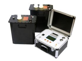
(including current transformers and voltage transformers) whether there is partial discharge phenomenon inside. This tester can help evaluate the insulation status of transformers, thereby preventing potential faults. Below is an overview of an article about transformer partial discharge tester.
Transformer Partial Discharge Tester
Overview
Transformer partial discharge tester is a professional device used to detect partial discharge phenomena in transformers. By capturing and analyzing signals such as electromagnetic waves, acoustic waves, or electrical pulses generated by partial discharge, it evaluates the insulation status of transformers. This detection is crucial for predicting and preventing potential faults in transformers.
Working Principle
The working principle of the transformer partial discharge tester is based on detecting and analyzing signals generated by partial discharge. When partial discharge occurs under test voltage, the tester detects high-frequency pulse current through a coupling capacitor. These pulse current signals are sent to the input data unit of the tester for processing. The specific process is as follows:
Signal Capture: Capture the pulse current generated by partial discharge through a coupling capacitor.
Signal Amplification: The pulse signal is first preliminarily amplified by a low-noise preamplifier.
Filtering Selection: Select the required frequency range through a filter amplifier to remove interference signals.
Signal Processing: After further amplification by the main amplifier, the signal is sent to the pulse peak unit for processing to display the peak value of the pulse.
Result Display: Display the discharge pulse and related data such as discharge amount, frequency, etc., through an oscilloscope or other display devices.
Key Components
Coupling Capacitor: Captures the pulse current generated by partial discharge.
Preamplifier: Preliminarily amplifies weak pulse signals.
Filter: Selects signals within a specific frequency range and eliminates interference.
Main Amplifier: Further amplifies the signal to a detectable level.
Display Unit: Displays graphical and numerical information of discharge pulses.
Technical Specifications
Capacitance range of testable objects: Typically supports capacitance ranges from a few picofarads to several thousand picofarads.
Detection sensitivity: Varies depending on model and brand.
Elliptical scanning time base:
Frequency: 50, 100, 150, 200, 400Hz.
Rotation: Rotatable in 30-degree increments, up to 120 degrees.
Working mode: Standard - Extended - Linear.
Input voltage range for high-frequency time base ellipse: 13~275V.
Display unit: Uses a 100×80mm rectangular oscilloscope tube, with brightness and focus adjustment knobs.
Usage Method
Startup Preparation: Ground the instrument properly, connect to power, and set the display mode to "Ellipse".
Calibration: Use a calibration pulse generator for calibration before applying test voltage.
Adjust Amplifier: Adjust the amplifier gain knob so that the height of the injected pulse is moderate, ensuring it matches the known injected charge.
Disconnect Calibration Connection: Remove the connection between the calibration pulse generator and the test circuit.
Test Operation: Connect the high-voltage test circuit power supply, slowly increase the test voltage, and note the first occurrence of continuous discharge.
Observe Discharge: Adjust the ellipse rotation button to place the discharge signal in the most favorable observation position.
Determine Inception Voltage: The voltage when the discharge amount exceeds the specified threshold is the partial discharge inception voltage.
Application Range
Current Transformers: Evaluate insulation status.
Voltage Transformers: Monitor partial discharge activity.
GIS (Gas Insulated Switchgear): Check the insulation performance of transformers in GIS.
High-Voltage Motors: Detect the insulation condition of transformers.
Precautions
Safe Operation: Ensure operators understand safety regulations to avoid electric shock risks.
Environmental Factors: Consider the influence of ambient temperature, humidity, etc., on test results.
Interference Sources: Minimize the impact of external interference sources as much as possible.
Regular Calibration: Ensure the accuracy and reliability of the instrument.
Conclusion
Transformer partial discharge tester is an important tool for evaluating the insulation status of transformers. By conducting regular partial discharge tests, potential insulation problems can be detected early, necessary maintenance measures can be taken, extending equipment life and reducing fault risks.
I hope this article can provide you with basic information about transformer partial discharge testers. If you have any further questions or need more specific details, please feel free to let me know.