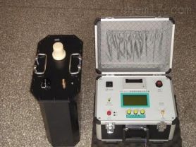
Partial Discharge (PD) refers to the phenomenon of charge release in localized areas within high-voltage equipment due to non-uniformities or defects in insulating materials. Although the energy involved is relatively small, long-term accumulation can accelerate insulation aging, ultimately leading to equipment failure or even system collapse. Therefore, the partial discharge detector has become an important preventive maintenance tool for detecting and assessing the insulation condition of power equipment.
Principles of Partial Discharge Detector
The partial discharge detector primarily operates based on the high-frequency pulse current measurement method (also known as the ERA method). When partial discharge occurs under test voltage, the detector's workflow is as follows:
Signal Acquisition: The high-frequency pulse current signal generated by partial discharge is introduced into the detector through a coupling capacitor.
Signal Processing: The signal is first amplified by a low-noise preamplifier, then filtered by a filter amplifier to select the desired frequency band, and further amplified by the main amplifier to achieve the required amplitude and generate zero-marker pulses.
Signal Display: The discharge pulses produce visible discharge pulses on the elliptical scanning baseline of the oscilloscope screen, and simultaneously are sent to the pulse peak meter to display their peak values.
Phase Correlation Analysis: To eliminate fixed-phase interference, a time window unit can control the test voltage and display the working time of the pulse peak meter in each cycle.
Composition and Usage of the Detector
A partial discharge detector typically consists of the following components:
Input Unit: Used to receive and preliminarily process pulse signals from the coupling capacitor.
Preamplifier: Used to reduce noise and amplify the signal.
Filter Amplifier: Selects the desired frequency band.
Main Amplifier: Further amplifies the signal to meet display requirements.
Oscilloscope: Displays the discharge pulse waveform.
Pulse Peak Meter: Displays the maximum value of the pulse.
Time Base Display Mode Switch: Used to set the scanning mode of the oscilloscope.
Usage Steps
Startup Preparation: Set the time base display mode switch to "Ellipse".
Calibration of Discharge Quantity: Before applying test voltage, use a calibration pulse generator to calibrate the detector.
Connect the calibration pulse generator and adjust the amplifier gain so that the injected pulse height is appropriate (usually not exceeding 2 cm on the oscilloscope screen).
Adjust the digital meter and pointer meter so that their readings match the injected known charge quantity.
Ensure that the fine adjustment knob of the amplifier remains unchanged during subsequent testing.
Connect the Test Object: Connect the detector to the test object to be inspected.
Apply Voltage: Gradually increase the test voltage until reaching the predetermined value.
Observation and Recording: Observe the discharge pulses on the oscilloscope and record the values displayed on the peak meter.
Data Analysis: Evaluate the partial discharge condition of the test object based on the recorded data.
Application Scenarios
Partial discharge detectors are suitable for preventive maintenance of various high-voltage equipment, including but not limited to:
Transformers
GIS (Gas-Insulated Switchgear)
High-voltage cables
Motors
Instrument transformers
Switchgear cabinets
Conclusion
The partial discharge detector is an indispensable testing tool in the power industry. Through precise measurement and analysis of partial discharges, it helps technical personnel detect insulation defects in equipment in a timely manner, effectively preventing equipment failures caused by partial discharges, thereby ensuring the safe and stable operation of the power system.
The above outlines the basic principles, usage methods, and applications of partial discharge detectors in power systems. Different models of partial discharge detectors may have different features and functions, so please refer to the specific user manual when using them.