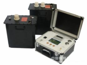
Partial discharge tester is an instrument specifically designed to detect partial discharge phenomena in power equipment. Partial discharge refers to the discharge occurring in localized areas of insulating materials under the influence of an electric field, which can gradually damage the insulation and eventually lead to equipment failure. Below is an overview of an article about partial discharge testers.
Partial Discharge Tester: Principles, Usage, and Applications
Introduction
Partial discharge testers are indispensable tools in the maintenance of power systems. They help engineers promptly identify potential issues in power equipment, thereby taking measures to prevent major accidents. This article will introduce the working principles, usage methods, and applications of partial discharge testers in power equipment maintenance.
Working Principles
Pulse Current Method: When partial discharge occurs, a brief high-frequency pulse current is generated in the circuit of the test object. By detecting these pulse currents, the presence and extent of partial discharge can be determined.
Signal Processing: The pulse current signal is transmitted to the detection impedance through a coupling capacitor, and then undergoes a series of signal processing steps, including amplification and filtering, before being displayed on the screen.
Display and Analysis: The graphical display on a color LCD screen allows observation of the waveform of partial discharge pulses, and software-assisted analysis of discharge characteristics.
Usage Methods
Startup Preparation:
Ensure the instrument is properly grounded and connect to a 220V AC power supply.
Set the display mode to "Ellipse".
Discharge Calibration:
Before applying the test voltage, use the calibration pulse generator for calibration.
Adjust the amplifier gain knob so that the injected pulse height is moderate and matches the digital voltmeter reading.
Test Operation:
Connect the high-voltage test circuit power supply and slowly increase the test voltage.
Observe the zero-mark pulse appearing on the ellipse.
Further increase the voltage, noting the first occurrence of sustained discharge; the voltage at this point is the partial discharge inception voltage.
Adjust the amplifier gain to ensure that the PC reading on the digital meter does not exceed 100.0.
Parameter Settings:
Adjust parameter settings according to different sensors to ensure measurement accuracy.
Safety Precautions:
Ensure all safety regulations are followed during the experiment.
When replacing sensors, turn off the output voltage first.
Applications
Power Equipment Maintenance: Regular testing of transformers, cables, switchgear, and other power equipment to assess insulation condition.
Fault Diagnosis: When abnormalities occur in power equipment, use partial discharge testers to locate the problem.
Quality Control: In the manufacturing process of power equipment, used to ensure that the electrical performance of products meets standards.
Conclusion
Partial discharge testers are key tools in modern power system maintenance. By regularly using these instruments for testing, power equipment failures can be effectively prevented, enhancing the reliability and safety of the power system.