It occurs when the impedances of the inductor (L) and capacitor (C) in the circuit cancel each other out. This means that at a specific frequency, the circuit as a whole behaves as a purely resistive element. This specific frequency is called the resonant frequency, which can be changed by adjusting the values of L and C. At the resonant frequency, the voltage and current in the circuit are in phase, causing the current in the circuit to reach its maximum value because the total impedance of the circuit is at its minimum at this point.
Minimum Impedance: At the resonant frequency, the total impedance of the circuit is at its minimum, theoretically determined only by the resistance (if present).
Maximum Current: Due to the minimum impedance, under the same input voltage, the current through the circuit reaches its maximum value.
Voltage Amplification: In the absence of an external resistor, high voltages may appear across the capacitor and inductor because of the energy exchange between them.
Application Areas
Radio Communication: Used in tuning circuits to select signals of specific frequencies.
Filter Design: Can be used to design band-pass or band-stop filters.
Power Factor Correction: Improves the efficiency of power systems by compensating for reactive power.
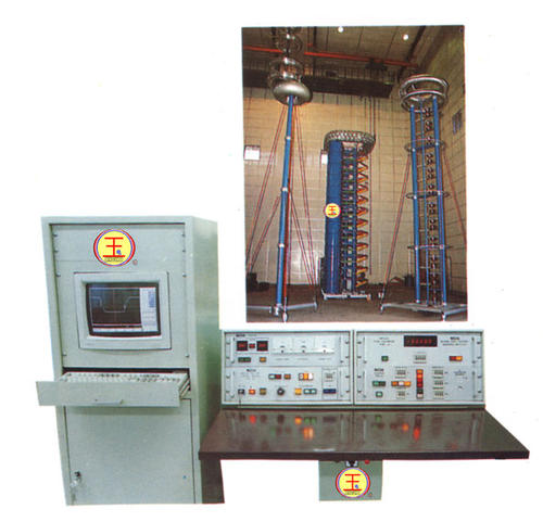
Testing Equipment: Such as resonant boosters, which use a small amount of input power to generate high voltage.
Precautions
Although series resonance has many useful applications, in practical operation it is necessary to avoid excessive current flow, which could damage circuit components or cause other safety issues. Therefore, when designing circuits that include series resonance, appropriate protective measures, such as fuses or circuit breakers, are usually considered.
If you are interested in specific calculations, experimental setups, or application examples of series resonance, you can ask more specific questions, and I will do my best to help.