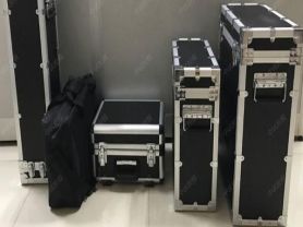
Partial discharge refers to the localized discharge phenomenon occurring in the insulation system of power equipment, which may be an early sign of insulation material deterioration. Below is an overview of an article about the single-channel partial discharge tester:
Single-Channel Partial Discharge Tester
Introduction
The safe operation of power equipment is crucial to the reliability of the entire power system. As a preventive maintenance measure, partial discharge detection can help identify potential insulation defects in power equipment, allowing timely measures to be taken to avoid failures.
Product Overview
Name: Single-Channel Partial Discharge Tester
Model: [Specific Model]
Manufacturer: Yangzhou Darui Electric Co., Ltd.
Main Features
Strong anti-interference capability: Uses digital filtering technology to effectively eliminate on-site interference.
High sensitivity: Can detect very weak partial discharge signals.
Easy operation: User-friendly interface and simple, clear operation procedures.
Accurate and reliable data: Test results are accurate with good repeatability.
Working Principle
The single-channel partial discharge tester works by detecting the pulse current signals generated by partial discharges inside power equipment. When partial discharge occurs inside power equipment, transient high-frequency pulse currents are generated in the equipment's electrical circuit. These pulse current signals can be coupled into the detection circuit through coupling capacitors (such as the distributed capacitance of the test object itself or externally added coupling capacitors). Subsequently, these pulse signals are captured by the input unit, amplified by a low-noise preamplifier, then filtered through a filter amplifier to select the desired frequency band, and finally further amplified by the main amplifier to achieve the required amplitude, while generating zero-marker pulses. The discharge pulses are displayed as visible pulses on the oscilloscope screen and simultaneously sent to the pulse peak meter to display their peak values.
Usage Steps
Startup preparation: Set the time base mode to "ellipse" mode.
Calibration: Correctly connect the calibration pulse generator and enable calibration.
After calibration: Disconnect the calibration connection line and remove the calibration pulse generator.
Connect high-voltage power: Connect the high-voltage test circuit power, turn on the zero-marker switch, and slowly increase the test voltage. Two zero-marker pulses appear on the ellipse on the display, with a phase difference of 180 degrees.
Adjust observation position: Rotate the "ellipse rotation" to a position convenient for observing discharges, typically where the zero-marker pulses are located on the upper left and lower right of the ellipse, then continuously increase the voltage and note any sustained discharges.
Determine the partial discharge inception voltage: When the discharge amount exceeds the specified low value, the voltage at that time is the partial discharge inception voltage.
Adjust display: At the set voltage, when discharge pulse signals are observed, adjust the amplifier switch so that the discharge pulse height is between 0.2 and 2 cm. The discharge amount is then the reading on the digital meter multiplied or divided by 10.
Application Scenarios
Power transformers: Used to detect partial discharge phenomena inside transformers.
High-voltage cables: Detect the insulation condition of high-voltage cables.
GIS equipment: Used to detect partial discharges in gas-insulated switchgear.
Other power equipment: Suitable for various power equipment requiring partial discharge detection.
Maintenance and Care
Regular calibration: Ensure detection accuracy.
Cleaning: Wipe the exterior of the instrument with a soft cloth.
Storage: Store in a dry and ventilated place.
Safety Precautions
Read before operation: Please read the user manual carefully.
Protective measures: Wear necessary personal protective equipment.
Avoid electric shock: Avoid contact with live parts during testing.
Conclusion
The single-channel partial discharge tester is an important health monitoring tool for power equipment, helping power maintenance personnel detect partial discharge issues in equipment in a timely manner, thereby improving the safety and reliability of the power system.
The above is a typical article overview of the single-channel partial discharge tester. Specific product features and parameters may vary depending on the manufacturer and model. If you need detailed information about a specific model, please provide the specific model name or other relevant information.