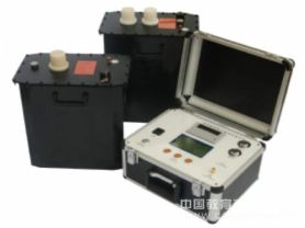
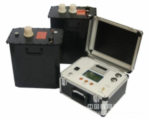
Chengshi Level 1 Xijun Electrical Ultra-Low Frequency Insulation Withstand Voltage Test Device
Dary Electric recommends for you:
Estimation method for test object current:
Calculation formula: I = 2πfCU
Principle of ultra-low frequency insulation withstand voltage test
The ultra-low frequency insulation withstand voltage test is actually an alternative method to the power frequency withstand voltage test. We know that when conducting power frequency withstand voltage tests on large generators, cables, and other test objects, due to their insulation layers having relatively large capacitance, a large capacity test transformer or resonant transformer is required. Such huge equipment is not only heavy and expensive but also very inconvenient to use. To solve this contradiction, the power sector has adopted a reduction in test frequency, thereby reducing the capacity of the test power supply. Years of theory and practice at home and abroad have proven that using 0.1Hz ultra-low frequency withstand voltage test instead of power frequency withstand voltage test not only has the same equivalence but also greatly reduces the size and weight of the equipment. Theoretically, the capacity is about one five-hundredth of the power frequency, and the operation is simple, with more advantages compared to power frequency tests. This is why developed countries generally adopt this method. The National Development and Reform Commission has formulated the industry standard "Test Method for Ultra-Low Frequency (0.1Hz) Withstand Voltage of 35kV and Below Cross-linked Polyethylene Insulated Power Cables". Our country is promoting this method, and this instrument is developed based on this need. It can be widely used in AC withstand voltage tests of cables and large high-voltage rotating motors.
Product Introduction
This product combines modern digital frequency conversion advanced technology, adopts microcomputer control, and the boosting, bucking, measurement, and protection are fully automated. Due to full electronization, it is small in size and light in weight, with a large screen LCD display that is clear and intuitive, and can display output waveforms and print test reports. The design indicators fully comply with the power industry standard "General Technical Conditions for Special Testing Instruments for Power Equipment, Part 4: General Technical Conditions for Ultra-Low Frequency High Voltage Generators", and it is very convenient to use. Currently, mechanical methods are used both domestically and internationally for modulation and demodulation to generate ultra-low frequency signals, so there are problems such as non-standard sine wave waveforms, large measurement errors, spark discharge in the high-voltage part, heavy equipment, and the second and fourth quadrants of the sine wave require high-power high-voltage resistors for discharge shaping, resulting in high overall power consumption of the equipment. This product can overcome these shortcomings and has the following features:
1. For rated voltage less than or equal to 50kV, the ultra-low frequency adopts a single-unit structure (one booster); for greater than 50kV, it adopts a series structure (two boosters in series), which greatly reduces the overall weight and enhances the load capacity. Moreover, the two boosters can be used separately as ultra-low frequency for lower voltage levels.
2. Current, voltage, and waveform data are directly sampled from the high-voltage side, so the data is accurate.
3、It has overvoltage protection function. When the output exceeds the set voltage limit, the instrument will stop for protection, with an action time of less than 20ms.
4、It has overcurrent protection function: designed with dual protection for high and low voltage. The high-voltage side can perform precise shutdown protection according to the set value; the low-voltage side will shut down for protection when the current exceeds the rated current, with action times less than 20ms.
5、The high-voltage output protection resistor is designed inside the booster, so no external protection resistor is needed.
6、Due to the adoption of high and low voltage closed-loop negative feedback control circuit, the output has no capacitive rise effect.
Technical Parameters
1.Rated output voltage: see Table 1
2.Output frequency: 0.1Hz, 0.05Hz, 0.02Hz
3.Load capacity: 0.1Hz max 1.1µF
0.05Hz max 2.2µF
0.02Hz max 5.5µF
4.Measurement accuracy: 3%
5.Voltage positive and negative peak error: ≤3%
6.Voltage waveform distortion: ≤5%
7.Usage conditions: indoor, outdoor; temperature: -10℃∽+40℃; humidity: ≤85%RH
8.Power fuse: see Table 1
9.Power supply: frequency 50Hz, voltage 220V±5%.
 Note: The above information and technical parameters are compiled and released by Yangzhou Dary Electric Co., Ltd.