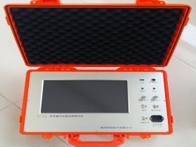
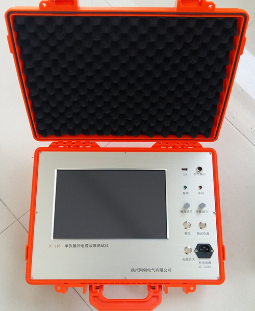
This instrument is suitable for overhead transmission lines of 35kV and above voltage levels. When a permanent single-phase grounding or line break fault occurs, as long as the faulty line is tested in the substation,the fault distance can be accurately measured, the faulty tower can be determined, which facilitates the repair personnel to quickly find the fault and shorten the repair time.
This instrument must be used on the premise that the line is de-energized. It has the characteristics of small size, easy portability, built-in battery for both AC and DC use, graphic and digital display functions, and convenient operation.
Principle
According to the theory of wave transmission, when a wave propagates on an overhead line and encounters an open circuit or short circuit point, it will be reflected, producing standing waves on the line. The frequency of the wave is different, and the positions of the peaks and troughs of the standing wave are different. By changing the frequency of the wave, the trough of the wave can be made to appear exactly at the injection point of the signal. Since the wave speed on the overhead line is fixed, the length of the line can be calculated when the wave speed is known.
Let: f: frequency of the injected signal;
v: speed of the injected signal along the line;
l: wavelength of the injected signal;
L: line length;
Because: f×l=v
Derived from theoretical formulas, it can be concluded:
For a line with a short circuit at the end, when the frequency of the injected signal changes from low to high, and the first standing wave trough appears at the injection point, the line length is half of the wavelength, that is:
L= l/2=0.5V/F;
For a line with an open circuit at the end, when the frequency of the injected signal changes from low to high, and the first standing wave trough appears at the injection point, the line length is one quarter of the wavelength, that is:
L=l/4=0.25V/F.
Based on this conclusion, the fault distance can be calculated.
This instrument is equipped with precise frequency measurement circuits and a module for detecting standing wave troughs, which can detect the frequency at which standing waves occur, and then convert the distance L between the fault point and the measurement point based on the existing wave speeds at various voltage levels. Since this instrument has a data memory circuit, it records data at various frequencies, allowing for further precise analysis after the test is completed.
3. Interface Introduction
After the instrument is turned on, it will automatically display the following graphical interface, where the curve part is the data waveform from the last sampling.
The main operation functions are analysis, sampling, and zooming.
The analysis function mainly changes the position of the marker line by controlling the "left shift" and "right shift" keys to find the frequency point where the lowest trough occurs. L at the bottom of the display screen indicates the fault distance, and it will provide corresponding distance data as the marker line position changes. A represents the amplitude of the standing wave point, and f is the frequency value of the frequency point marked by the current marker line.
Sampling is the process of measuring standing wave points.
Zooming is to compress and enlarge the measured curve in the frequency axis (x-axis) direction (change of fineness) in combination with analysis.
The open circuit or short circuit prompt is the fault state indication of the line end being open circuit or short circuit ground, obtained by the instrument based on mathematical model analysis after measurement and sampling, and it is also the data for distance calculation.
The voltage level indication below the distance indication is mainly used to select the wave speed of the line under that voltage level, and its selection corresponds to the voltage level of the measured line.
Note: The above information and technical parameters are compiled and released by Yangzhou Dary Electric Co., Ltd.