Abstract
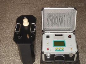
A single-channel partial discharge tester is a specialized device used to detect partial discharge phenomena inside power equipment. By capturing signals such as electromagnetic waves, acoustic waves, or electrical pulses generated by partial discharges within the equipment, this instrument can effectively diagnose and locate potential insulation defects, which is of great significance for preventing failures and accidents in power equipment. This article will provide a detailed introduction to the working principles, operational steps, and applications of the single-channel partial discharge tester in the power industry.
Introduction
Partial discharge refers to the phenomenon of charge release occurring in localized areas within the insulating medium of power equipment. Prolonged existence may lead to the deterioration of insulating materials and even eventual breakdown failures. The single-channel partial discharge tester can detect and locate these potential problem points by capturing signals generated by partial discharges, which is crucial for the safe operation of power systems.
Working Principles
The working principles of the single-channel partial discharge tester mainly include the following steps:
Signal Capture: When partial discharge occurs inside power equipment, signals such as electromagnetic waves, acoustic waves, or electrical pulses are generated.
Signal Amplification: The built-in preamplifier captures these signals and amplifies them.
Signal Processing: The amplified signals are passed through filters to select signals within a specific frequency range, eliminating interference.
Display and Analysis: The processed signals are displayed on the display unit in the form of graphs and numerical values, used to analyze the number and intensity of discharge pulses.
Operational Steps
Startup Preparation:
Adjust the time base mode to the "ellipse" mode.
Ensure all connections are correct and the power connection is error-free.
Calibration:
Correctly connect the calibration pulse generator and enable the calibration function.
After calibration, disconnect the calibration connection wires and remove the calibration pulse generator.
Connecting the Test Circuit:
Connect the power supply of the high-voltage test circuit.
Turn on the zero-marker switch and slowly increase the test voltage.
Two zero-marker pulses appear on the display ellipse, with a phase difference of 180 degrees.
Observing Discharge Phenomena:
Rotate the "ellipse rotation" knob to a position convenient for observing the discharge.
Continuously increase the voltage, paying attention to any sustained discharges that appear.
When the discharge amount exceeds the specified low value, the voltage at that time is the partial discharge inception voltage.
Adjusting the Amplifier:
At the set voltage, when discharge pulse signals are observed, adjust the amplifier switch.
Make the discharge pulse height between 0.2 and 2 cm; the discharge amount is the reading on the digital meter multiplied or divided by 10.
Recording Data:
Record the inception voltage and extinction voltage of the partial discharge.
Analyze the number and intensity of discharge pulses.
Safe Shutdown:
After testing, turn off the power switch.
Disconnect all connections and clean up the site.
Precautions
Ensure all operations are conducted under the guidance of professionals.
Closely monitor signal changes during the test.
After the test, ensure complete power-off before proceeding with any further operations.
Application Cases
Case Study: Provide examples illustrating the effectiveness of the single-channel partial discharge tester in practical applications, such as detecting partial discharge phenomena inside certain power equipment, and subsequently taking measures for repair or replacement.
Development Trends and Challenges
Technological Progress: With the advancement of electronic technology, the accuracy and stability of new single-channel partial discharge testers continue to improve.
Data Analysis: Utilizing big data and artificial intelligence technologies for more in-depth data analysis to enhance detection efficiency and accuracy.
Integration and Portability: Instruments are developing towards greater integration and portability, facilitating on-site use.
Conclusion
The single-channel partial discharge tester, as one of the important testing tools in the power industry, is of great significance for ensuring the safety and reliability of power equipment. With continuous technological advancements, its applications in the power industry will become increasingly widespread.
This framework provides a basic structure, and you can add more details and technical information according to specific needs. If you require more detailed content or specific experimental data, please let me know your specific requirements.