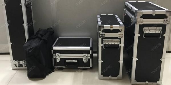
A transformer partial discharge tester is a specialized device used to detect partial discharge phenomena inside power transformers. Partial discharge detection is of great significance for assessing the insulation condition of transformers and preventing faults. This article will provide a detailed introduction to the working principle, characteristics, application scope, usage methods, and maintenance suggestions of the transformer partial discharge tester.
Working Principle
The working principle of the transformer partial discharge tester is based on the physical phenomena generated during partial discharge, particularly ultrasonic signals and electromagnetic wave signals. When partial discharge occurs inside a transformer, a series of physical phenomena are generated, including:
Electrical pulses: Current pulses generated by partial discharge.
Ultrasound: Ultrasonic signals generated by partial discharge.
Electromagnetic radiation: Electromagnetic wave signals generated by partial discharge.
Light: Optical signals generated by partial discharge.
Chemical reactions: Chemical changes triggered by partial discharge.
The transformer partial discharge tester captures these signals through built-in sensors and processes and analyzes them through internal circuits and software to determine whether partial discharge phenomena exist and further assess the degree of discharge.
Main Features
The characteristics of the transformer partial discharge tester include
High sensitivity: Capable of detecting weak ultrasonic and electromagnetic wave signals.
Easy operation: Features an intuitive user interface for convenient on-site operation.
Data recording and analysis: Can record detection data and analyze it through software.
Multiple display modes: Supports various display modes such as elliptical, linear, and sinusoidal, facilitating observation of discharge pulses.
Auxiliary functions: Some advanced models also feature auxiliary zero-marking systems, linear/logarithmic dual-function pointer meters, and digital meters.
Strong anti-interference: Utilizes digital filtering technology to effectively eliminate on-site interference.
Remote positioning: Can remotely locate the source of partial discharge.
Technical Parameters
Ultrasonic sensor type: Built-in ultrasonic sensor.
Electromagnetic wave sensor type: Built-in electromagnetic wave sensor.
Frequency range: Ultrasonic typically 20kHz to 100kHz, electromagnetic waves typically hundreds of kHz to several MHz.
Sensitivity: Typically capable of detecting tiny ultrasonic and electromagnetic wave signals.
Battery life: Generally several hours.
Display unit: Uses a color LCD screen, supporting multiple display modes.
Data storage: Built-in memory, capable of storing a large amount of detection data.
Application Scope
The transformer partial discharge tester is widely used in the maintenance and repair of power systems, including but not limited to:
Power transformers: Used to monitor partial discharge conditions inside transformers.
High-voltage switchgear: Monitors partial discharge phenomena inside switchgear.
Cable terminations: Detects partial discharge in cable terminations.
Instrument transformers: Detects partial discharge in voltage transformers and current transformers.
Power cables: Assesses the insulation condition of cables.
Usage Methods
Startup preparation: Ensure the instrument is properly grounded, connect to ~220V power supply, and set the display mode to "Ellipse" (default).
Discharge quantity calibration: After wiring according to the diagram, use the calibration pulse generator to calibrate before applying test voltage.
Adjust amplifier gain: Make the injected pulse height appropriate (about 2cm on the oscilloscope screen), so that the digital voltmeter reading matches the known injected charge. After adjustment, the fine adjustment knob position of the amplifier must not be changed and should remain the same as during calibration.
Disconnect the calibration pulse generator from the test circuit.
Test operation: Turn on the high-voltage test circuit power, slowly increase the test voltage, and note the first occurrence of continuous discharge. When the discharge quantity exceeds the specified minimum value, the voltage is the partial discharge inception voltage. Use the "Starting Phase Selection" button switch to position the discharge signal at the most favorable point on the ellipse for observation.
Maintenance Suggestions
Regular inspection: Regularly check whether the equipment functions properly and whether the battery is sufficiently charged.
Cleaning and maintenance: Gently wipe the instrument surface with a soft cloth, avoiding solvents or corrosive substances.
Storage conditions: Store in a dry, ventilated place, avoiding high temperature or humid environments.
Fuse check: When the terminal is powered but the transformer partial discharge tester cannot start normally, check whether the fuse on the power socket is intact. If it is blown, replace it with a new fuse.
Prevent exposure: When used outdoors, try to stay in a shaded area to avoid prolonged exposure to direct sunlight.
Conclusion
The transformer partial discharge tester is one of the indispensable tools in power system maintenance and plays an important role in preventing and reducing power equipment failures. By comprehensively considering the above factors, users can proficiently master the usage methods of the transformer partial discharge tester and perform appropriate maintenance to ensure its long-term stable operation.
Please adjust the content of this article according to your specific needs, and if you need more detailed information or specific data, feel free to let me know.