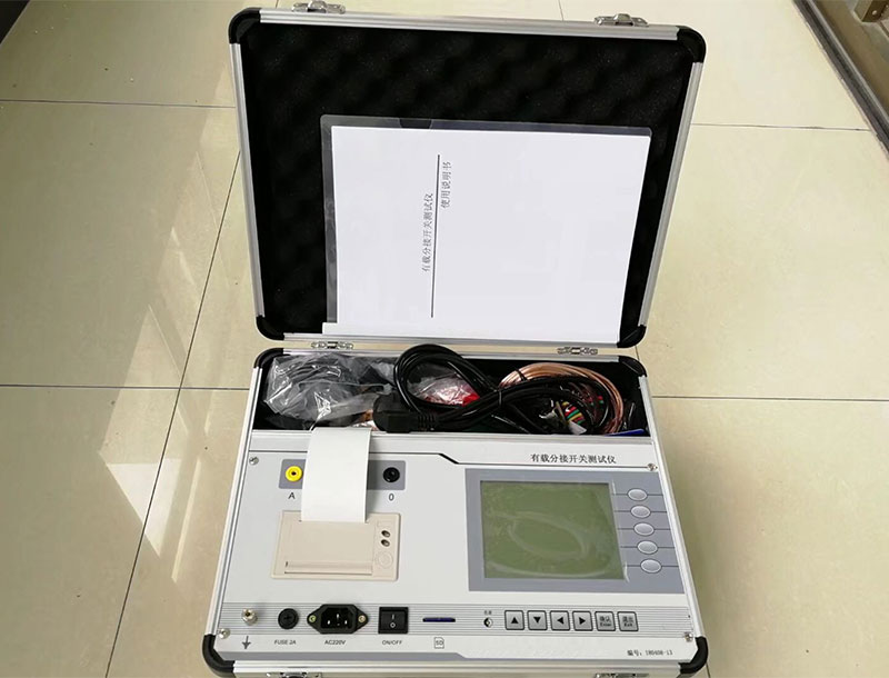
High Voltage Switch Dynamic Characteristic Tester
1. Closing/Opening Time: The time interval from the instant the closing (opening) command is received to the instant when all pole contacts touch (separate). 2. Closing/Opening Synchronism: The maximum time difference among the instants when contacts of each break touch (separate). 3. Bounce Time: During the closing (opening) operation of the switch, the time from the first contact (separation) of the moving and static contacts to the final stable contact (separation). 4. Operating Time: (Contact Operating Time) The time interval from the instant the closing (opening) command is received to the instant when the contacts just start to move. 5. Bounce Count: The number of times the moving and static contacts separate (close) during the opening (closing) operation. 6. Bounce Amplitude: The maximum rebound value of the moving contact during its movement. 7. Travel: The distance from the initial position of the moving contact to any position during closing and opening operations. 8. Opening Gap: The total gap between the contacts of one pole or any connected conductive parts when in the open position. 9. Over-travel: The distance the moving contact continues to move after the contacts touch during the closing operation. 10. Excess Travel: The difference between the maximum travel during the moving contact's movement and the stable travel after settling in closing and opening operations. 11. Instantaneous Closing (Opening) Speed: The speed of the moving contact at the instant of touching (separating) the static contact during the closing (opening) operation. 12. Average Speed: The ratio of the travel to the time during the entire movement of the moving contact in the closing (opening) operation. 13. Arcing Time (Contact Touch Time): In a close-open operation, the time interval from the instant all pole contacts touch to the instant when the arcing contacts of all poles separate during the subsequent opening operation.
(1) A-type panel: Please pinch the elastic clips on both sides of the printer frame with your fingers, push the entire printer into the mounting hole of the instrument or equipment panel, and check whether the printer is installed securely. (2) D-type and F-type front paper-loading panel: Installation is extremely simple and convenient. Insert the entire printer into the mounting hole of the instrument or equipment panel, clamp the printer from behind the equipment panel with the plastic clips and tighten the screws. ◆The general paper loading process is as follows ① Remove the front cover of the printer. ② For A-type panel micro printers, they must be removed from the instrument panel. Note: The micro printer power must be turned off before operation. D-type, F-type front paper-loading panel, and T-type desktop can skip this step. ③ Remove the paper roll shaft, install a new paper roll, place the shaft back into the guide slot of the printer, and ensure the paper roll shaft is securely installed and will not fall out. ④ Cut the paper end into a triangle or trim it neatly. ⑤ Turn on the printer power. After the printer advances a little paper, press the SEL key to turn off the SEL indicator, then press the LF key to rotate the print head. Manually feed the paper head into the paper inlet below the print head. The paper will slowly enter the print head until it emerges from the front of the print head. Then press the LF or SEL key to stop the print head rotation → close the printer cover and thread the paper out through the paper slot on the front cover. ◆Replacing the Ribbon Cartridge Ribbon replacement is only for dot matrix printers. Thermal printers only require special thermal paper and do not need ribbon replacement (consumables). Note: Thermal paper has two sides; only the front side can be printed on. ◆The process of replacing the ribbon cartridge is as follows ① Open the printer front cover. ② First lift the right end of the ribbon cartridge, then lift the left end (the end with the knob) to remove the cartridge. ③ Gently place the left end of the new ribbon cartridge onto the gear shaft of the print head, turn the knob on the cartridge in the direction of the arrow until the cartridge's end falls into place, then lower the right end of the cartridge. ④ Install the printer cover. First hook the upper part of the front cover onto the frame, aligning the indicator lights and buttons, then press the lower part of the front cover toward the frame with slight force to snap it into place.