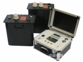
In the fields of power systems, electronic engineering, and materials science, the dielectric loss tester is an important device used to evaluate the performance of various insulating materials and dielectrics. By precisely measuring the energy loss of a dielectric under an alternating electric field, this tester provides key data for ensuring the safe operation of electrical equipment and material screening. This article will delve into the working principle, application fields, operation steps, and precautions of the dielectric loss tester.
Working Principle
The core task of the dielectric loss tester is to measure the energy loss of a dielectric under alternating voltage, i.e., the dielectric loss factor (tangent delta, tan δ), which mainly originates from the polarization process and conductivity of the dielectric. The tester applies an alternating voltage to the sample under test, then measures the resulting current, and calculates the dielectric loss factor by combining other known parameters in the circuit.
Specifically, the tester includes a standard circuit and a test circuit. The former contains a known and stable capacitor, while the latter is the dielectric under test. By comparing the current amplitude and phase difference of the two, and using vector operations and Fourier transform filtering techniques, the capacitance value and dielectric loss factor of the medium can be accurately calculated.
Application Fields
The dielectric loss tester is widely used in the following fields:
Power equipment testing: Used for dielectric loss testing of transformers, cables, capacitors, and other power equipment to assess the aging degree of insulating materials and the overall performance of the equipment.
Material research: In the development of new materials, it is used to screen high-performance insulating materials with low dielectric loss.
Quality control: On production lines, it is used to monitor product quality and ensure that the dielectric performance of finished products meets standards.
Operation Steps
Preparation phase: Ensure the tester is reliably grounded, connect the test leads as required, turn on the power, and set the measurement mode (power frequency or heterodyne frequency), connection method, and measurement voltage.
Parameter setting: According to test requirements, select the appropriate measurement voltage (e.g., 10kV) and measurement frequency (power frequency or heterodyne frequency). Power frequency measurement is fast but may be inaccurate in interfering environments, while heterodyne frequency measurement is more accurate but time-consuming.
Start testing: Execute the measurement procedure, and the tester will automatically perform data acquisition and calculation to obtain the dielectric loss factor and other related parameters.
Data interpretation: Analyze the test results to evaluate the performance of the dielectric, and repeat the test if necessary to verify the results.
Precautions
When conducting high-voltage tests, always follow safety regulations to ensure the safety of operators.
Before testing, check the condition of the sample under test to avoid testing under humid or contaminated conditions to obtain accurate results.
Set the test voltage correctly; too high may cause dielectric breakdown, while too low may not accurately reflect the true loss condition.
Conclusion
The dielectric loss tester is an indispensable testing tool in the fields of power, electronics, and materials science. By accurately evaluating dielectric performance, it provides a scientific basis for equipment maintenance, material screening, and quality control. With continuous technological advancement, new dielectric loss testers are improving in accuracy, automation, and user-friendliness, bringing greater convenience to research and applications in related fields.