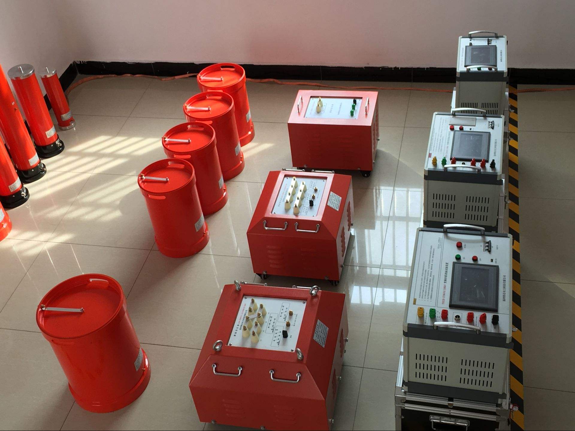
Comprehensive Transformer Characteristics Testing Instrument
Comprehensive Transformer Characteristics Testing Instrument is specifically designed for relay protection professionals to test current transformer volt-ampere characteristics, ratio testing, and polarity discrimination. It can also be used for transformer polarity discrimination testing. It is a multifunctional testing instrument with a high performance-to-price ratio.
This instrument adopts high-efficiency, low-consumption high-quality materials and specially wound voltage boosters, with microcontroller microprocessor for data acquisition, analysis, and storage. It has a built-in micro printer that can print test data and curves. When measuring CT ratio, it can automatically calculate the ratio value. One person can complete all testing tasks. This instrument is lightweight, easy to operate, and has unique performance, making it an indispensable tool for field personnel.
Instrument Features
1. Single power supply 220AC, safer and more reliable to use (completely abandoning the dangerous 380V live wire);
2. Single unit output 2500V/1000A;
3. Can test transformers with 5A/5A—25000A/5A, 5A/1A—5000A/1A;
4. Only need to set the test voltage and current, the device can automatically and quickly complete the test, no training required, easy to master;
5. Large output capacity, full functions, high precision, and unique performance;
6. 320×240 large LCD display, full Chinese graphical interface;
7. Uses imported rotary mouse, making setting test values faster and simpler;
8. During testing, the volt-ampere curve can be directly displayed, with clear graphics, intuitive and convenient;
9. Comes with a fast printer, supporting on-site printing of test results;
10. Comes with a large-capacity memory that can save 1000 sets of test data, which will not be lost after power failure and can be accessed at any time;
11. USB communication interface, convenient for connecting to new laptops, can upload test data for editing, saving, or printing;
12. Integrates multiple instrument functions into one, easily achieving one machine with multiple uses, effectively improving work efficiency and reducing labor intensity.
13. Supports offline and online testing
Technical Specifications
1. Input voltage: AC 220V or 380V, 50HZ, automatic identification of input voltage.
2. Working environment temperature: 0~40℃.
3. Input voltage: When input AC 220V, output 0-500V.
When input AC 380V, output 0-1000V.
Current: Maximum instantaneous current, 600A when testing ratio.
When input AC 220V, output 0-400A.
When input AC 380V, output 0-600A.
15A when testing volt-ampere characteristics.
4. Digital voltmeter measurement range: 0-9999V; Resolution: 0.1V.
When displaying current: 0-9.9A; Resolution: 0.1mA.
5. Digital ammeter measurement range: 0~3000A; Resolution: 0.01A.
6. Error: 1≤1%, U≤1%.
7. When testing CT ratio, it can automatically calculate the ratio value and print the data and calculation results.
8. When testing volt-ampere characteristics, it stores and prints 20 sets of current and voltage values and the volt-ampere characteristic curve.
9. Dimensions: Length×Width×Height=470×340×260mm3.
10. Weight: 23Kg.
Precautions
1. Current transformer secondary winding should not have a grounding point.
2. The voltage regulator switch and output switch should be in the off position before connecting or disconnecting wires.
3. The device should be reliably grounded before testing.
4. After testing, the voltage should be returned to zero promptly, and prolonged exposure to high voltage and high current is strictly prohibited.
◆Common Fault Maintenance
1. After turning on the power switch, the LCD shows no display.
Solution: Check if the power input line is properly connected.
2. No voltage or current output during volt-ampere characteristic test.
Solution: Check if the voltage regulator switch (overcurrent protection) is turned on.
3. Voltage but no current during volt-ampere characteristic test.
Solution: Check if the test loop wires are properly connected.
4. No current output during ratio test.
Solution: Check if the primary test wire is properly connected.
5. The voltage regulator switch trips during startup test.
Solution: Check if the transformer grounding point is disconnected.
◆LCD Contrast Adjustment
1. When the LCD display is too dark or too bright, it can be adjusted using the potentiometer (terminal 4) on the panel.
◆Replacing Printer Paper
1. First, disconnect the power, open the printer panel, pinch both ends of the telescopic paper shaft, remove the paper roll shaft from the printer, slide the new paper roll onto the paper shaft, pinch both ends of the paper shaft, place the paper shaft back in place, release your hands and the paper shaft will snap into the paper shaft holder, confirm the paper shaft is securely installed.
2. Cut the paper head of the new paper roll into a triangular shape with scissors, turn on the power, press the paper feed button for 3 seconds, the printer head will rotate, then push the paper roll with the cut paper head into the paper inlet at the bottom of the printer head, the paper will be fed into the printer head, after a section of paper comes out from the paper outlet, turn off the power, then thread the paper head out through the paper outlet on the front cover, and close the printer panel.
Instrument Usage Method
Volt-Ampere Characteristic Test
1. The user should appropriately select the input voltage based on the volt-ampere characteristics of the device under test. When output above 500V is required, input 380V voltage.
2. Ground the instrument reliably.
3. Check that the current transformer has no grounding point.
4. Switch the switch "16" to the volt-ampere position.
5. Connect the instrument output and voltage measurement to the secondary side of the current transformer (as shown in Figure 2).
6. Check that the voltage regulator is at zero, turn on the "24" switch, press the reset button once, the indicator light above it will light up, and the microprocessor is now in waiting storage state.
7. Turn on the output switch 4, slowly rotate the voltage regulator clockwise, when storage is needed, press the storage button, the indicator light above the storage button will light up, and the internal buzzer will sound. (Note: During the entire measurement process, it is not allowed to turn the voltage regulator back. The dwell time when adjusting to high current should be as short as possible.)
8. Up to 20 sets of current and voltage values can be stored.
9. After storage is complete, return the voltage regulator to zero.
10. Press the print button to print the test data and the volt-ampere characteristic dot matrix chart. The voltage axis has three ranges, and the range selection is automatic, automatically selecting a certain range based on the maximum sampled voltage:
0—199V each grid represents 10V, 200V—499V each grid represents 25V, 500V—2000V each grid represents 50V. The current axis has two ranges, and the range selection is automatic, automatically selecting a certain range based on the maximum sampled current.
0—7A each grid represents 0.25A, 7A—40A each grid represents 0.5A
11. Press the reset button once to reset, then the test can be repeated.
12. After the test, turn off the "4" switch and the "24" switch, and unplug the connecting wires.