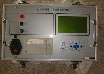
Fully Automatic Volt-Ampere Characteristic Tester Test Operation Method and Procedure
7.2 Volt-Ampere Characteristic and Error Curve Test
In the main interface, click the "Test" menu, and in the pop-up submenu, click the "Volt-Ampere Characteristic Test" command to open the volt-ampere characteristic and error curve test window (as shown in Figure 33 below)
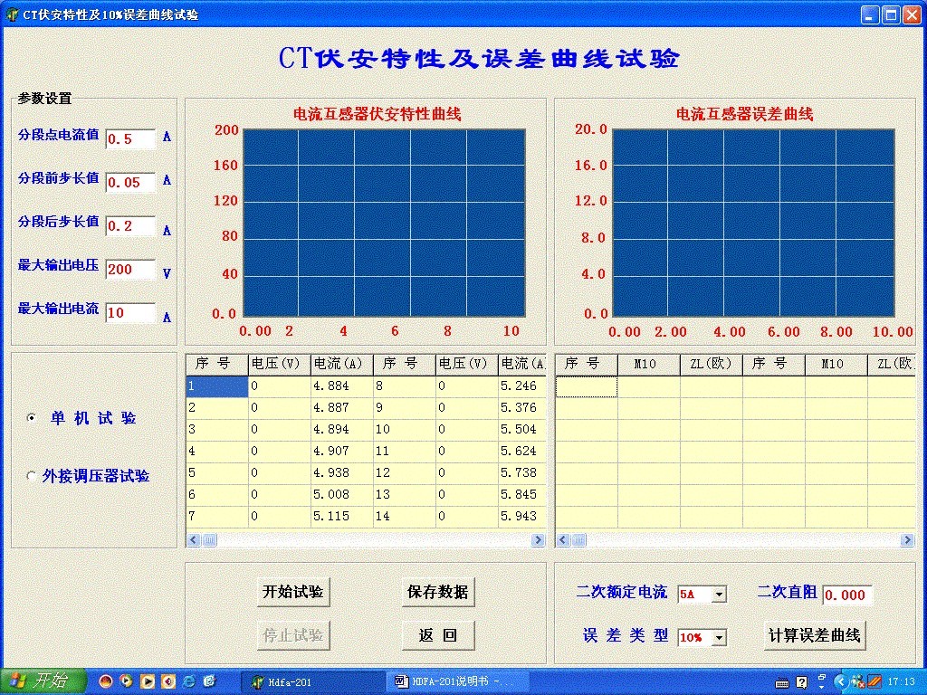
Figure 33
7.2.1 Interface Parameter Description
Segmentation Point Current Value: During the test, to ensure that the points on the volt-ampere characteristic curve before and after the inflection point are distributed reasonably, a segmentation point is set, and two different current step sizes are used for testing before and after this point. The segmentation point current value is set based on estimated values or measured inflection point values, with a range of (0 - 20) A.
Step Size Before Segmentation: The step current step size before the segmentation point, with a range of (0.001 - 2.000) A
Step Size After Segmentation: The step current step size after the segmentation point, with a range of (0.001 - 2.000) A
Maximum Output Voltage: The maximum voltage that the secondary side of the current transformer can withstand, with a range of (0 - 1500) V.
Maximum Output Current: The maximum current that the secondary side of the current transformer can withstand, with a range of (0 - 20) A.
Standalone Test: When testing with the built-in voltage regulator of the device, click "Standalone Test".
External Voltage Regulator Test: When testing with an external voltage regulator is required, click "External Voltage Regulator Test".
7.2.2 Test Method
7.2.2.1 Volt-Ampere Characteristic Curve
The test principle and wiring method of the fully automatic volt-ampere characteristic tester are the same as those of the standalone test. After wiring is completed, click "Start Test" to begin the test. At this time, the device automatically increases the voltage and current step by step according to the voltage, current, and step size values for testing. Each measured point will be automatically displayed in the data display box with voltage and current values, and the volt-ampere characteristic curve will be automatically plotted. During the test, you can click "Stop Test" at any time to terminate the test.
7.2.2.2 Error Curve
After completing the volt-ampere characteristic test, set the "Secondary Rated Current" and "Error Type" respectively, then click the "Calculate Error Curve" option to calculate and display the error data based on the measured volt-ampere characteristic data, and automatically plot the 5% or 10% error curve.
7.3 Transformation Ratio Polarity Test, Secondary Load, and Demagnetization Test
In the main interface of the fully automatic volt-ampere characteristic tester, click the "Test" menu, and in the pop-up submenu, click "Transformation Ratio Polarity Test" to open the transformation ratio polarity test, secondary load test, and demagnetization test window (as shown in Figure 34 below)

Figure 34
7.3.1 Transformation Ratio Polarity Test
7.3.1.1 Parameter Settings
Maximum Test Current Applied on Primary Side: The current to be applied to the primary side of the current transformer during the transformation ratio polarity test, with a range of 0 - 600A.
Secondary Rated Current: The rated current of the secondary side of the current transformer, 1A or 5A.
Primary Current: The actual current value applied to the primary side during the transformation ratio polarity test.
Secondary Current: The actual current value measured on the secondary side during the transformation ratio polarity test.
Transformation Ratio: The actual transformation ratio calculated based on the actual currents measured on the primary and secondary sides during the transformation ratio polarity test.
Polarity: The actual polarity measured during the transformation ratio polarity test.
"Keep the output for a certain time when testing the secondary side circuit" is used to maintain the primary side output current for a period of time. The duration of this time is related to the current value; the larger the current, the shorter the time.
7.3.1.2 Test Method
After setting the parameters, click "Start Test" to perform the test. After the test is completed, the transformation ratio and polarity values will be automatically displayed. During the test, you can click "Stop Test" at any time to terminate the test.
7.3.2 Secondary Load Test
After setting the secondary rated current value, click "Start Test" to perform the test. After the test is completed, the secondary impedance and secondary load will be automatically displayed. During the test, you can click "Stop Test" at any time to terminate the test.
7.3.3 Demagnetization Test
After setting the "Current Value Applied on Primary Side", click "Start Test" to complete the demagnetization test. During the test, you can click "Stop Test" at any time to terminate the test.