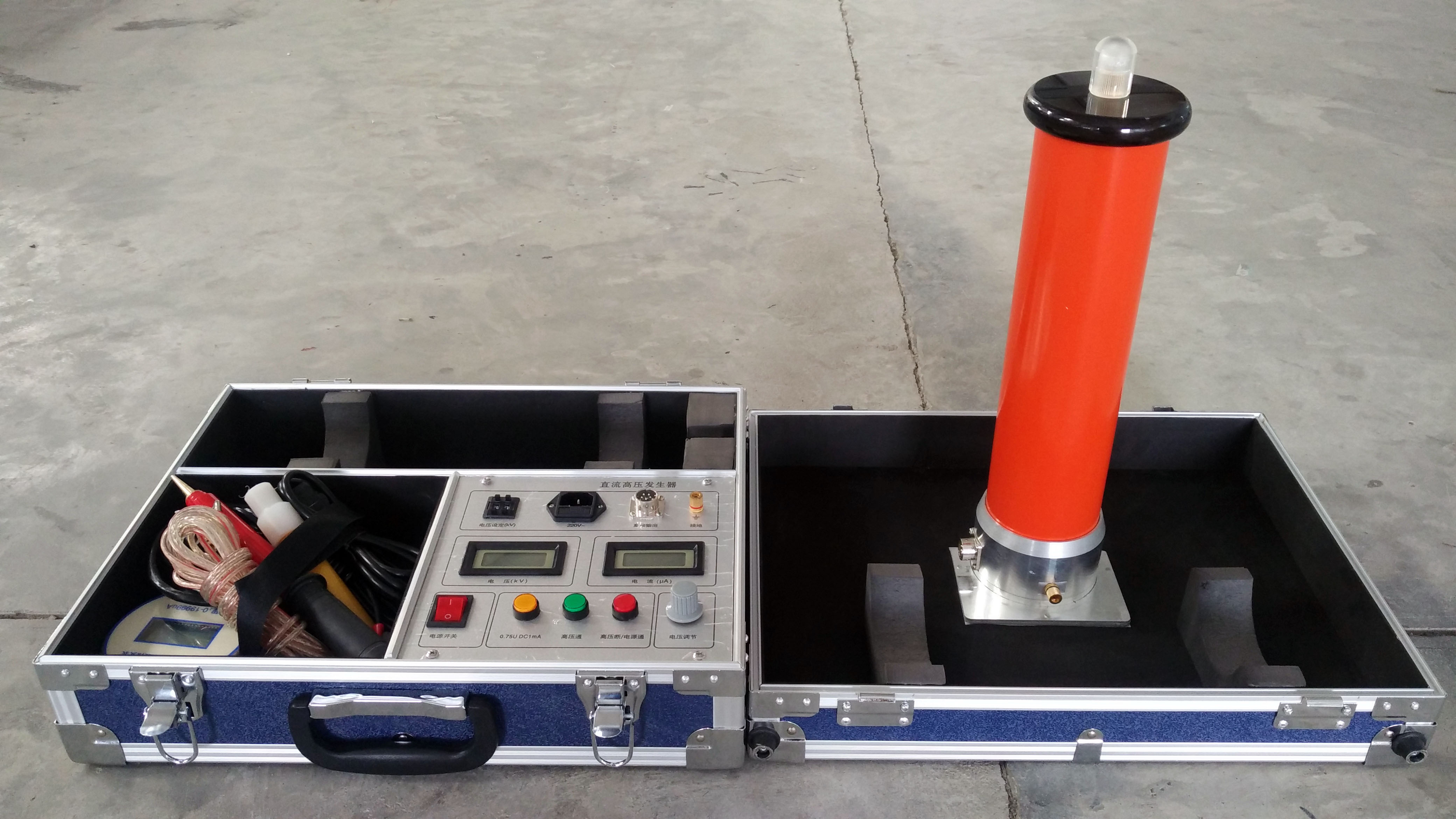
300kv/5ma DC High Voltage Generator New DC High Voltage Generator
Operating Instructions:
● The indicator lights, switches, knobs, etc. on the control box are clearly marked. When reading these operating instructions, please refer to the component names on the control box panel.
● On the side of the high-voltage tower chassis, there is a seven-pin socket for connecting the control box cable. On the side of the chassis, there is a copper terminal for grounding connection.
● The accompanying high-voltage shielded ammeter is a digital microammeter. The socket on the top of the meter is the wire socket for connecting to the test object, and it also serves as the power switch. When not in use, please unplug the plug to automatically turn off the power. When replacing the battery, open the screws on the top cover, replace the battery, and then close the cover and tighten the screws. For the flat round meter, open the back cover to replace the battery.
1. Connect the grounding terminal on the control box panel to the grounding terminal on the high-voltage tower using the grounding wire, and securely connect it to the grounding wire of the site or laboratory. To ensure the safety of you and the equipment, please repeatedly check the grounding wire to ensure good grounding at all parts.
Use the provided seven-core cable to connect the control box and the high-voltage tower. Both ends of the cable have the same quick connector. Note that the notch on the side of the connector should align with the thick protrusion inside the socket, insert it, and then turn it clockwise to tighten. (Either end of the cable can be connected to the control box or the high-voltage tower.)
Connect the power cord. The power supply is single-phase AC 220V, 50Hz.
2. Turn on the power switch. At this time, the power switch light (green) and the panel meter light up. The high-voltage indicator light (green) lights up. If the high-voltage alarm buzzer is in the on position, it will sound to alert the operator that high voltage is being applied. At this time, turn the high-voltage output adjustment knob clockwise to increase the voltage. The voltmeter displays the voltage kV value on the load test object, and the ammeter displays the sum of the current flowing through the test object and all leakage currents, but does not include the current of the built-in high-voltage divider. The current is displayed in microamperes (uA).
If the power switch is turned on, the high-voltage indicator light (green) does not light up, and the "return to zero" light (red) in the fault display is on, it means that the high-voltage output adjustment knob is not at the zero position. Please turn this knob counterclockwise to the "zero" position, and also return the fine-tuning voltage knob to the zero position. At this time, the "return to zero" light goes out, and then turn it clockwise to increase the voltage.
3. If overvoltage protection within the rated output voltage range is not required, turn the overvoltage protection setting knob clockwise to the maximum value. Otherwise, when the output voltage exceeds the rated output voltage, automatic protection will activate and cut off the high voltage. If overvoltage protection within the rated output voltage range is required, please increase the voltage under no-load conditions following the above steps to the preset protection voltage, then slowly turn the overvoltage protection setting knob counterclockwise to the desired voltage. When overvoltage protection activates, the "overvoltage" indicator light lights up. Keep the overvoltage protection setting knob at this position, return the voltage increase knob to zero, and turn off the power. Connect the test object. When the voltage increases beyond the preset voltage, the high voltage will be automatically cut off.
4. When faults such as overvoltage or overcurrent occur, the high voltage is automatically cut off, the high-voltage indicator light (green) goes out, the buzzer stops sounding, and the corresponding fault indicator light lights up, indicating that the test object is short-circuited. To restart, return the high-voltage output adjustment knob to zero, also return the fine-tuning knob to zero, then turn off the power switch, and then turn on the power switch again to reset the protection and increase the voltage again.
● For normal shutdown, first turn the high-voltage adjustment knob counterclockwise to zero, then return the fine-tuning voltage knob to zero, and finally turn off the power switch.
● The power switch also serves as the protection reset switch. Therefore, when a fault indicator light (except the return-to-zero indicator light) lights up, turn off the power switch and then turn it on again to reset the protection and increase the voltage again.
5. When the load is a large capacitive load, to avoid triggering overcurrent protection due to excessive charging current, the voltage increase speed should be appropriately slowed down. After the test is completed, turn the output voltage adjustment knob counterclockwise to zero. At this time, the voltmeter still displays the voltage on the test object. Please wait until the test object discharges to below 20kV through the high-voltage tower before using the grounding rod to discharge, to ensure safety.
Precautions:
1. To ensure personal safety, we repeatedly remind users to pay attention to good grounding of the control box and high-voltage tower, as well as the discharge of the test object and high-voltage tower after shutdown.
2. Do not block the upper and lower ventilation holes of the control box, and prevent foreign objects from falling in through the holes. If the control box has a fan, check regularly whether the fan is operating normally.
3. When the insulating cylinder of the high-voltage tower is dirty, wipe it clean with a dry cloth. Do not use organic solvents such as alcohol or gasoline for cleaning. You can use detergent to clean the surface of the insulating cylinder, and use it only after it is air-dried. When transporting or not in use, place it in the aluminum alloy case.
4. When replacing the fuse, replace it with the ampere rating indicated next to the fuse holder.
5. If the high-voltage shielded microammeter displays "LOW BAT", replace the 9V battery to avoid measurement errors. When not in use, turn off the power.
6. Do not open the control box or high-voltage tower without permission, as this will affect the product warranty. The manufacturer is not responsible for any self-disassembly.
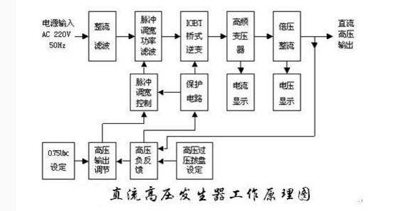
Electrical Principle Block Diagram: