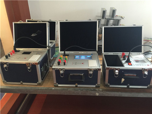
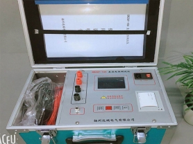
Introduction to Inductive Load DC Resistance Tester:
Connect all high and low voltage current and potential test leads to the transformer at once; no need to reconnect test leads during the test.
For star-connected windings, the instrument can test A0, B0, C0 phase resistances simultaneously in three-phase mode, saving test time.
For three-phase five-limb transformers with low-voltage delta connection, the instrument uses an automatic magnetic assist method internally, which is faster than directly using high current for testing.
Displays and prints all test data for high, medium, and low voltage windings, automatically calculates three-phase unbalance, and can print resistance values converted to rated temperature.
In three-phase testing, A0 data is tested first, then all three phases are tested simultaneously, solving the issue where the neutral point lead resistance cannot be tested during simultaneous three-phase testing, making test data closer to single-phase test values.
Inductive Load DC Resistance Tester
The instrument should be reliably grounded. After connecting test leads, turn on the power. During the output current test, do not remove test leads to avoid accidents. After completion, wait until the current arc indication ends or the audible and visual alarm stops before turning off the power and removing test leads.
When using three-channel mode to measure on-load tap-changing transformers, tap points can be switched under load, saving charging time.
For off-load tap-changing transformers, wait until the discharge indication alarm stops before switching tap points or changing gears.
Magnetic assist testing is mainly for three-phase five-limb transformers with delta-connected low-voltage windings (if low-voltage winding is delta-connected and charging is slow during test, magnetic assist method can be used).
Wiring and Operation
1. Connect the instrument to external AC 220V power with the power cord, and connect the grounding terminal to earth with the grounding wire.
2. For two-winding transformers, connect the four test clamps (yellow, green, red, black) of the high-voltage test leads to the A, B, C, O bushings on the high-voltage side respectively. If only A, B, C bushings are available, leave the black test clamp floating. Connect the other end of the test leads to the corresponding terminals on the instrument. Connect the four test clamps (yellow, green, red, black) of the low-voltage test leads to the a, b, c, o bushings on the low-voltage side respectively. If only a, b, c bushings are available, leave the black test clamp floating. Connect the other end of the test leads to the corresponding terminals on the instrument.
Note: No need to reconnect leads during the entire test process.
3. For three-winding transformers, after testing high and low voltage windings, reconnect the four test clamps of the high-voltage test leads to the medium-voltage side for testing.
4. For single-phase transformers, connect the yellow and black test clamps of the high-voltage test leads to the high-voltage side, and the yellow and black test clamps of the low-voltage test leads to the low-voltage side.
5. The dedicated test leads provided with the instrument have current and voltage lines designed on the same clamp, making wiring simple and convenient.
Parameters:
| Specification |
10A |
20A |
40A |
| Test Current |
1mA 10mA 1A 5A 10A |
1A 5A 10A 20A |
2.5A 5A 10A 20A 40A |
| Measurement Range |
1mA: 1Ω~20kΩ
10mA: 1Ω~2kΩ
1A: 10mΩ~20Ω
5A: 1mΩ~4Ω
10A: 1mΩ~2Ω |
1A: 10mΩ~20Ω
5A: 1mΩ~4Ω
10A: 1mΩ~2Ω
20A: 1mΩ~1Ω |
2.5A: 10mΩ~8Ω
5A: 1mΩ~4Ω
10A: 1mΩ~2Ω
20A: 1mΩ~1Ω
40A: 1mΩ~500mΩ |
| Measurement Accuracy |
±0.2% (full scale) ±2 digits |
| Data Storage |
255 items |
| Display |
LCD display |
| Maximum Resolution |
0.1μΩ |
| Power Supply |
AC 220V±22V, 50Hz±2 Hz |
| Maximum Power Consumption |
300 W /500W/1200W |
| Operating Environment |
Ambient temperature: 0°~40° Relative humidity: ≤80% |
| Dimensions |
200╳400╳280(mm) |
| Weight |
6kg/10kg/32 kg |