DARU Electric recommends:
Product Introduction:
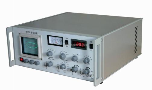
The high-efficiency transformer partial discharge tester is based on the advanced theories in the field of partial discharge instrument research at home and abroad, adopting advanced technology and circuits, and has been continuously improved through extensive user feedback. It retains the advantages and functions of previous generations while being more refined in design, more convenient in use, and more reliable in performance.
Technical Specifications:
I. Main Unit Parameters
1. Capacitance range of test objects: 6pF~250µF
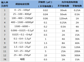
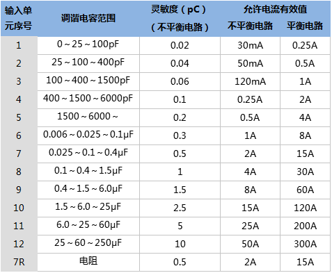
2. Detection sensitivity and allowable current (see Table 1)
3. Elliptical scanning time base
(1) Frequency: 50 (internal), 100, 150, 200, 400Hz
(2) Rotation: in steps of 30°, rotatable 360°
(3) Operating modes: Ellipse — Expanded — Straight line
(4) High-frequency time base ellipse can be adjusted to normal size according to input voltage (10~250V), with power consumption <1VA and automatic overload protection
4. Display unit
Uses a 124×104mm2 rectangular oscilloscope tube with brightness and focus adjustment knobs
5. Amplifier
(1) 3dB low-frequency cutoff fL: 10, 20, 40kHz selectable
(2) 3dB high-frequency cutoff fH: 80, 200, 300kHz selectable
(3) Gain adjustment: coarse adjustment in 6 steps, with 20±1dB difference between steps, fine adjustment range >20dB
(4) Asymmetry of positive and negative pulse response <1dB
6. Time window
(1) Window width: adjustable, 15°~ 150° at 50Hz
(2) Window position: each window can be rotated 0°~ 170°
(3) Two time windows can be opened separately or simultaneously
7. Pulse peak meter
(1) Linear scale pointer meter 0—100 error ±5% (based on full scale)
(2) Logarithmic scale pointer meter 0—10—100 error ±5% (based on full scale)
(3) Digital meter: 3.5-digit LED digital display 0—100 error: ±3% (based on full scale)
8. Test voltage meter
(1) Range 100kV (using 100kV voltage divider resistor R)
(2) Display: 3.5-digit digital voltmeter
(3) Error: ±3%
9. Zero marking system
(1) The zero marker of the internal zero generator can change polarity and rotate 0~180° to match the polarity of the true zero position generated by the voltage resistor R
(2) The zero marker is synchronized with all elliptical scanning frequencies
10. Structure
(1) Dimensions: 530×550×220mm3
(2) Weight: approximately 22kg
II. Pulse Generator Parameters
1. Output charge levels: 5pC, 10pC, 20pC, 50pC
2. Polarity: alternating positive and negative
3. Repetition frequency: 1.2kHz
4. Frequency variation range: >±100Hz
5. Pulse rise time: <60nS
6. Pulse fall time: >100uS
7. Injection capacitor: 10pF
8. Calibration charge error: Eq≤±10%
9. Dimensions: 160×125×50mm3
10. Weight: 0.5kg
11. Battery: 6F22 9V
Product Aliases:
Partial Discharge Detector, Partial Discharge Tester, PD Tester, Partial Discharge Test System
Performance Features:
1. The partial discharge detector features high detection sensitivity, wide applicability to test objects, and high signal-to-noise ratio.
2. It uses a large-screen oscilloscope tube for clear display of test waveforms, with high-frequency elliptical scanning (power consumption less than 1VA), a large dynamic range amplification system, multiple frequency band combinations (nine types), an auxiliary zero marking system, and both linear and logarithmic pointer meters as well as a digital meter, allowing simultaneous display of discharge pulse magnitude.
3. The partial discharge detector is a powerful auxiliary tool for researching and developing new high-voltage electrical products and improving product quality, as well as an effective test instrument for on-site assessment of equipment condition.
4. When used in conjunction with the calibration pulse generator, the partial discharge detector is especially suitable for power departments, manufacturers, and scientific research institutions.
Note: The above information and technical parameters are compiled and released by Yangzhou DARU Electric Co., Ltd.