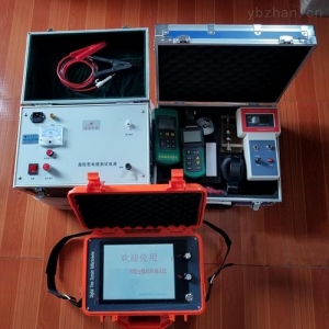
After power-on and reset, the first screen displayed is the copyright logo, as shown in Figure (6)
Schematic diagram of the power-on state.
When the year, month, and day are entered sequentially, it automatically enters the second screen, or press "Reset" to directly enter the work selection menu.
"Work Selection" menu
"Pulse" mode menu: selecting 1 from the main menu enters the pulse menu.
Select keys according to actual testing needs.
3. Introduction to the main test display interface
The main interface is divided into three areas. The upper part is the calculation parameters and results area, as shown in Figure (7).
The middle is the waveform display (wiring diagram before sampling) area, where one or two waveforms can be displayed as needed. Vertical cursor lines and time scales are also displayed.
The lower part is the status and date display area. The status displays are Pulse Direct Flash, Surge 1, and Surge 2. In pulse mode for measuring full length and faults, it prompts to select speed; for measuring speed, it prompts to enter the full length value. In flash test mode, only speed selection is prompted.
Section 3 Cable Fault Testing Steps and Test Method Selection
Before testing cable faults, besides mastering the performance and operation methods of this instrument, test personnel must first determine the nature of the cable fault in order to adopt appropriate working and testing methods.
First, use a megohmmeter or multimeter to measure the insulation resistance of each phase to ground and between phases at one end of the cable. Based on the resistance value, determine whether it is a low-resistance short circuit, open circuit, or high-resistance flashover fault.
When the resistance is below 200-300 ohms, it is a low-resistance fault; 0 to tens of ohms indicates a short circuit fault; extremely high resistance to infinity indicates an open or broken circuit fault. To confirm an open circuit, you can also connect the cable terminals together and use a multimeter at the starting end to measure the resistance of the shorted two phases. Such faults can be directly measured using the low-voltage pulse method.
When the resistance is very high (hundreds of megohms to gigohms) and there is instantaneous discharge during high-voltage testing, such faults are generally called flashover faults and can be determined using the DC high-voltage flash test method.
High-resistance faults: resistance higher than low-resistance faults, and determined by the DC high-voltage flash test method during high-voltage testing.
After rough testing in a certain manner, proceed to pinpoint the fault location. If necessary, find the cable path and measure the cable length or distance.
Note: The above information and technical parameters are compiled and released by Yangzhou DARUI Electric Co., Ltd.