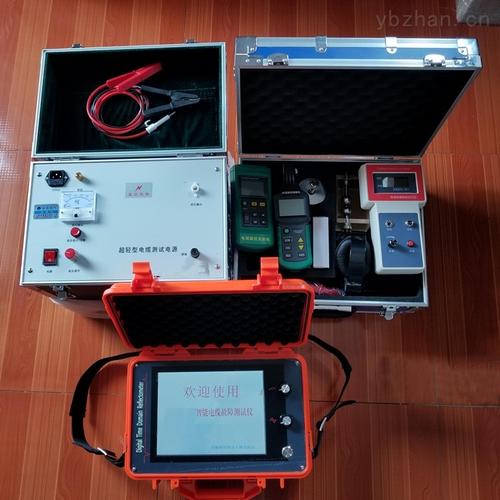
Scope of Application:The ST-2000 Intelligent Cable Fault Detector is used to measure various power cables, high-frequency coaxial cables, local telephone cables, and buried wires laid evenly with two or more conductors of different cross-sections and different media, for high and low resistance, short circuit, open circuit, broken wire, as well as high resistance leakage and high resistance flashover faults.
Working Modes: Low-voltage pulse, DC high-voltage flashover, and impulse high-voltage flashover.
Sampling Rate: 25MHz.
Internal Transmitted Pulse Width and Amplitude: 0.2us, 100~120V; 2us, 150~160V.
Storage Capacity: 8Kbyte, can be divided into two storage areas to store and display two sampled waveforms for comparison measurement.
Display Resolution: V/50m, where V is the propagation speed in m/us.
Display Mode: 320×240 LCD with backlight.
Printing Method: A micro printer is installed on the main panel to record test date and test waveform data.
Power Supply and Consumption: AC 200V ± 10% or internal DC power supply, power consumption not greater than 10W; DC 6V (7AH) power consumption not greater than 6W.
Dimensions: 300×400×180mm (length×width×height).
Section 2: Instrument Panel and Operating Functions
The panel and keyboard of the high-voltage cable fault tester are shown in Figure (2):
Computer USB Communication Port: Currently only for professional production and technical personnel to debug and input programs.
Instrument Indicator Lights: Respectively for charging, undervoltage, and pulse width (0.2/2).
Input/Output Socket: The instrument uses BNC-50KY (Q9) socket, connected to the cable for test signal input and output.
Input Amplitude: Used to adjust the input and output pulse amplitude. Adjust according to the waveform displayed on the screen during use. If adjusted too small, the pulse reflection is very small, and sampling may even fail, as shown in Figure (3). If adjusted too large, the reflected pulses connect with the baseline without intersection, or the baseline may become a slanted line, as shown in Figure (4). Generally, before sampling, rotate the input amplitude knob to about 1/3, then adjust according to the waveform size and resample.
Contrast Adjustment Knob: Adjust this knob to make the text display clear, without stripes and with a clean background.
Pulse Width Selection Button: When the button is up, the instrument outputs 0.2uS pulses; when pressed, it outputs 2uS. In actual cable testing, generally use 0.2uS first; if the reflection is too small after no reflection, then use 2uS.
Power Switch: The instrument uses a switch with indicator.
Display Screen: The instrument uses a 320×240 dot matrix LCD with backlight for displaying operation menus, test waveforms, test results, dates, etc.
Micro Printer: This instrument uses a 4-pin 24-line micro printer for printing test waveforms, test data, and test dates.
SEL Key: Self-test key. Press this key to print self-test data parameters to check the printer head and driving circuit.
LP Key: Paper feed key. Press this key to activate the paper feed mechanism and stop the print pins. Use this key when replacing printer paper.
Note: The above information and technical parameters are compiled and released by Yangzhou Darui Electric Co., Ltd.