Darui Electric recommends:
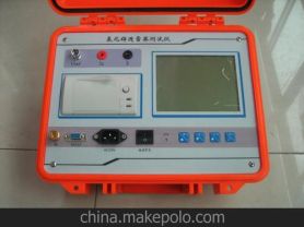
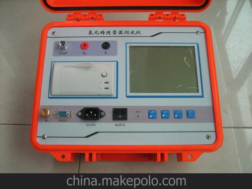
I. Features of LYYHX6000 Wireless Zinc Oxide Arrester Live Tester
1) This device features a large LCD screen, full Chinese menu operation, and is easy to use.
2) High-precision sampling and processing circuits, advanced Fourier harmonic analysis technology, ensuring more reliable data.
3) The instrument uses a unique high-speed magnetic isolation digital sensor to directly collect input voltage and current signals, ensuring data reliability and safety.
4) LYYHX6000 Wireless Zinc Oxide Arrester Live Tester can use electric field induction or wireless transmission methods instead of PT secondary wiring.
5) This instrument can directly measure resistive current without connecting to PT secondary.
6) This instrument offers six testing methods, providing testers with a wide range of options. (PT secondary method, induction method, wireless transmission method, single current synchronization method, PT secondary synchronization method, wireless synchronization method)
7) This instrument can measure three phases simultaneously with automatic compensation, making it very convenient to use.
8) LYYHX6000 has a rechargeable battery, calendar clock, micro printer, and can store 120 sets of measurement data;
Operation Modes
1. The instrument inputs PT secondary voltage as a reference signal, and simultaneously inputs the MOA current signal. Through Fourier transform, the voltage fundamental wave U1, current fundamental peak Ix1p, and current-voltage angle Φ can be obtained. Therefore, the component in phase with the voltage is the resistive current fundamental peak (Ir1p), and the orthogonal component is the capacitive current fundamental peak (Ic1p):
Ir1p=Ix1pCOSΦ Ic1p=Ix1pSINΦ
Considering that δ=90°—Φ is equivalent to the dielectric loss angle, directly using Φ to evaluate MOA is also very simple: without "interphase interference", Φ is mostly between 81° and 86°. According to the requirement that "resistive current should not exceed 25% of total current", Φ should not be less than 75.5°. Refer to the table below for segmented evaluation of MOA performance:
Performance <75° 75°~77° 78°~80° 81°~83° 84°~89° >89°
Φ Poor Bad Fair Good Excellent Interference
In fact, attention should be paid when Φ<80°.
Grounding:
Connect the ground wire before measurement, and disconnect it last after measurement! If the grounding point has paint or rust, it must be cleaned thoroughly.
Reference Voltage
One end of the reference voltage signal line is inserted into the reference voltage socket, and the other end is connected to the PT secondary low-voltage output of the phase under test: the small black clip connects to the neutral point (x), and the small red clip connects to the phase voltage under test (a/b/c). For external application method, connect to the measurement winding of the step-up transformer. If the PT is far away, an extension cable can be used.
Current Signal
First insert the leakage current signal line plug into the instrument, then clip the other end (or attach it via an insulating rod) to the upper end of the MOA discharge counter of the phase under test. In the laboratory, the MOA without a discharge counter can be placed on an insulating board, and the current signal can be taken from the lower end of the MOA. Extension cables cannot be used for the current signal.
 Note: The above information and technical parameters are compiled and released by Yangzhou Darui Electric Co., Ltd.