Variable Frequency Series Resonance Withstand Voltage Device ManufacturerVariable Frequency Series Resonance Withstand Voltage Device Manufacturer
Main Features:
☆Compact size, light weight, easy operation
☆Blue screen displays test data, test status, and provides real-time operation step prompts
☆Flexible setting of test voltage, frequency range, pressurization time, and protection current
☆Test results can calculate the capacitance of the test object
☆Equipped with computer communication interface for data exchange and test data management with a computer
☆High resolution: frequency resolution of 0.01Hz
☆High safety and reliability. The device has overcurrent, overvoltage, IPM, and discharge protection functions, effectively ensuring personal and equipment safety.
☆Test results can be printed
Main Technical Parameters and Features:
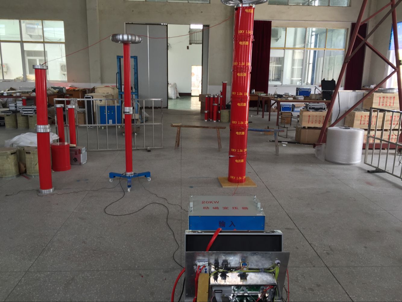
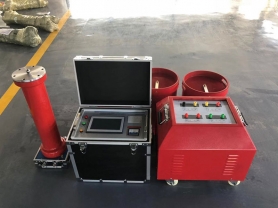
The variable frequency series resonance complete set adopts 16-bit fine frequency and voltage regulation software, 10KHz carrier frequency, SPWM technology, and imported original IPM integrated modules and other components. It consists of a variable frequency voltage regulating power supply, excitation transformer, high-voltage reactor, high-precision capacitive voltage divider, and compensation capacitor.
Ambient temperature: -25 to 50°C
Working humidity: ≤90%
Altitude: ≤3000M
Power supply: AC 220V single-phase 50Hz (above 10KW: AC 380V three-phase four-wire, 50Hz)
Frequency adjustment range: 30~300 Hz (can be widened according to user requirements)
System measurement accuracy: Class 1
Frequency adjustment resolution: 0.1 Hz
Instability: ≤0.05%
Output waveform: Sine wave
Waveform distortion rate: ≤0.5%
Noise: ≤60dB
Reactor Q value: 30~200
Introduction:
The variable frequency resonance test device is widely used in electric power, metallurgy, petroleum, chemical and other industries, suitable for handover and preventive tests of large-capacity, high-voltage capacitive test objects.
The series resonance test equipment is mainly used for variable frequency AC withstand voltage tests of 10kV, 35kV, 110kV cross-linked rubber-plastic power cables, and 66kV, 110kV, 220kV gas-insulated switchgear (GIS), as well as power frequency AC withstand voltage tests of hydro and thermal generators or power transformers. Its basic principle is to use adjustable (30--300Hz) series resonance test equipment to resonate with the capacitance of the test object to generate an AC test voltage.
Technical Parameters:
|
Rated output voltage
|
0~130KV (RMS) and below
|
|
|
Output frequency
|
20~300Hz
|
|
|
Resonant voltage waveform
|
Sine wave, waveform distortion rate ≤1%
|
|
|
Full load working time
|
Continuous working time 6min
|
|
|
System quality factor
|
≥20 at maximum load
|
|
|
Frequency adjustment fineness
|
0.1Hz, instability ≤0.01%
|
|
|
Working power supply
|
220V or 380V single-phase mains
|
|
Product Applications:
|
Product Model Name
|
Basic Configuration
|
|
|
Control Box
|
Reactor
|
Excitation Transformer
|
Voltage Divider
|
Applicable Object
|
|
|
44/22
|
2.5kW
|
1A/22kV two units
|
2.5kVA/1kV
|
25kV
|
10kV cable ≤1kM (300mm²)
|
|
|
88/22
|
4kW
|
2A/22kV two units
|
4kVA/1kV
|
25kV
|
10kV cable ≤2kM (300mm²)
|
|
|
132/22
|
5kW
|
2A/22kV three units
|
6kVA/1/3kV
|
70kV
|
10kV cable ≤3kM (300mm²)
|
|
|
35kV cable ≤0.7kM (300mm²)
|
|
|
198/22
|
10kW
|
1.5A/22kV six units
|
10kVA/1/3kV
|
70kV
|
10kV cable ≤4kM (300mm²)
|
|
|
35kV cable ≤1kM (300mm²)
|
|
|
264/22
|
15kW
|
2A/22kV six units
|
15kVA/1/3kV
|
70kV
|
10kV cable ≤6kM (300mm²)
|
|
|
35kV cable ≤1kM (300mm²)
|
|
|
396/22
|
15kW
|
3A/22kV six units
|
15kVA/1/3kV
|
70kV
|
10kV cable ≤8kM (300mm²)
|
|
|
35kV cable ≤2kM (300mm²)
|
|
|
640/22
|
25kW
|
2.5A/32kV eight units
|
25kVA/1/3/5kV
|
130kV
|
10kV cable ≤10kM (300mm²)
|
|
|
35kV cable ≤3kM (400mm²)
|
|
|
110kV cable ≤1kM (300mm²)
|
|
|
640/22
|
50kW
|
5A/32kV eight units
|
50kVA/1/3/5kV
|
130kV
|
10kV cable ≤20kM (300mm²)
|
|
|
35kV cable ≤8kM (300mm²)
|
|
|
110kV cable ≤2kM (400mm²)
|
|
Product Advantages:
1. The required power supply capacity is greatly reduced. The series resonance test device uses the resonance between the reactor and the capacitance of the test object to generate the required high voltage and large current. In the entire system, the power supply only needs to provide the active power consumption part of the system. Therefore, the power required for the test is only 1/Q times the test capacity (Q is the quality factor).
2. The weight and volume of the equipment are greatly reduced. In the series resonance power supply, not only the bulky high-power voltage regulating device and the ordinary high-power power frequency test transformer are omitted, but also the resonant excitation power supply only needs 1/Q of the test capacity, greatly reducing the system weight and volume, generally 1/5 to 1/10 of ordinary test devices.
3. Improve the output voltage waveform. The resonant power supply is a resonant filter circuit, which can improve the waveform distortion of the output voltage, obtain a good sine wave, and effectively prevent false breakdown of the test object caused by harmonic peaks.
4. Prevent large short-circuit current from burning the fault point. In the resonant state, when the insulation weakness of the test object is broken down, the circuit immediately detunes (capacitance changes, resonance condition not satisfied), and the loop current rapidly drops to 1/Q of the normal test current. In contrast, when using parallel resonance or traditional test transformer for AC withstand voltage test, the breakdown current immediately rises dozens of times. Comparing the two, the short-circuit current and breakdown current differ by hundreds of times. Therefore, series resonance can effectively find insulation weaknesses without the worry of large short-circuit current burning the fault point.
5. No recovery overvoltage will occur. When the test object breaks down and flashes over, due to the loss of resonance conditions, the high voltage immediately disappears, the arc is immediately extinguished, and the protection circuit of the device operates to cut off the output.