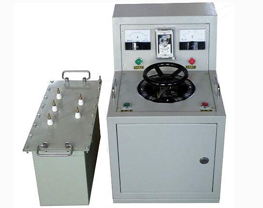
JY-180kVA/60kV Series Resonance Withstand Voltage Test Detailed Information
JY-180kVA/60kV Series Resonance Withstand Voltage Test Device Overview:
Variable frequency series resonance is suitable for AC withstand voltage tests of various large power transformers, power cables, steam and hydro generators, and other capacitive equipment, which must be strictly conducted periodically according to test regulations. Under power frequency conditions, due to the large capacitance of the test object or the high test voltage requirements, the power supply capacity of the test device also has correspondingly high requirements. Traditional power frequency withstand voltage devices often have large single-piece volume, heavy weight, are inconvenient for on-site handling, and are not easy to combine arbitrarily, resulting in poor flexibility.
JY-180kVA/60kV Series Resonance Withstand Voltage Test Device Technical Solution
1. Basic Principle of Variable Frequency Series Resonance:
The variable frequency series resonance withstand voltage test uses the inductance of the reactor and the capacitance of the test object to form an LC series circuit, adjusts the voltage frequency output by the variable frequency power supply, achieves series-parallel resonance, and obtains high voltage on the test object. It is a new method for high-voltage testing, highly praised by experts, and has been widely used domestically and internationally.
2. Characteristics of Variable Frequency Series Resonance Test Device:
The variable frequency series resonance test device has large output capacity, high output voltage, and can arbitrarily combine reactors for AC withstand voltage tests of different test objects.
The variable frequency series resonance test device has small size, light weight, each piece weighing no more than 50kg, especially convenient for field tests.
The variable frequency series resonance test device has good protection functions, including overvoltage protection, overcurrent protection, time protection, flashover protection, overheating protection, module protection, etc.
The variable frequency series resonance test device is extremely simple to operate and has both manual and automatic modes.
The variable frequency series resonance test device adopts a large screen, making test data clear at a glance, and can print test results.
The variable frequency series resonance test device has no risk of overvoltage after test object breakdown, causing relatively little damage to the test object.
The variable frequency series resonance test device requires small power supply capacity, only a fraction of that required for power frequency transformer testing, solving the problem of difficulty in finding power sources on site.
3. Scope of Application:
Suitable for AC withstand voltage test of 400mm2/35kV cross-linked cable with a length of 2000m.
4. Environmental Conditions for Use:
1 Ambient temperature: -10℃~40℃
2 Relative humidity: not greater than 90%
3 Altitude: below 2500 meters
5. Standards Referenced and Implemented for Equipment Manufacturing
1DL/T849.6—2004 High-voltage resonant test devices;
2GB 6450—1986 Dry-type power transformers;
3DL/T848.2—2004 Test transformers;
4GB/10229—1988 Reactors;
5GB/T11920—1989 General technical conditions for control devices;
6GB/T16927.1—1997 High-voltage test techniques;
7IEC358—1990 Coupling capacitors and capacitor dividers.
6. Equipment Configuration List
| Name | Specification/Model | Unit | Quantity | Dimensions (mm) | Weight (kg) |
| Frequency conversion power supply | 15kVA | Unit | 1 | 420×280×380 | 22 |
| Excitation transformer | 15kVA/2.5kV×2 | Unit | 1 | 450×300×650 | 75 |
| High-voltage reactor | 25kV/3A//40H | Unit | 4 | φ330×470 | (each)65 |
| Capacitive voltage divider | 50kV/0.001uF | Unit | 1 | φ150×750 | 8 |
| Compensation capacitor | 50kV/0.0125uF | Unit | 1 | φ250×750 | 18 |
| Accessories |
| Set | 1 |
|
|
7. Main Functions and Parameters:
7.1 System Parameters of Frequency Conversion Resonance Test Device
7.1.1.Instrument input voltage: 220V±10% 50Hz;
Power input voltage: 380V±10% 50Hz;
7.1.2.Rated output voltage adjustment range: 0 ~ 50kV;
7.1.3.Maximum test capacity: 300kVA;
7.1.4.Resonant voltage waveform: sine wave, distortion rate: ≤0.5%;
7.1.5.Output voltage instability: ≤0.5%;
7.1.6.Output frequency range: 25~320Hz;
7.1.7.Frequency adjustment resolution: 0.01Hz;
7.1.8.Quality factor Q value: not less than 50 under rated load;
7.1.9.Insulation level: withstand voltage of 1.2 times rated voltage for 1min;
7.1.10.Continuous operation time at rated current not less than 30 min;
7.1.11.Voltage measurement accuracy: class 1;
7.1.12.Noise: ≤45dB;
7.1.13.The device is equipped with the following protection functions:
The equipment has manual test, automatic tuning, and automatic test;
Overvoltage protection, overcurrent protection, discharge protection, power-off protection, zero-start protection.
Test data displayed on large screen, Chinese menu, printable output, printer is embedded.
7.2 Frequency Conversion Power Supply:
7.2.1.Rated output capacity: 15kVA;
7.2.2.Instrument power: 220V±10% 50Hz;
Power supply: 380V±10% 50Hz;
7.2.3.Rated input current: 39.5A;
7.2.4.Rated output voltage: 0-340V adjustable, single-phase, output voltage instability 0.05%;
7.2.5.Rated output current: 44A;
7.2.6.Frequency adjustment range: 25~320Hz;
7.2.7.Continuous operation at rated capacity: temperature rise ≤60K within specified working time;
7.2.8.Display the following parameters:
a. Frequency, voltage, and current output after frequency conversion;
b. Overvoltage protection voltage value, which can be arbitrarily set. When the output voltage of the complete device reaches the protection setting, the complete device can be automatically cut off;
c. Overcurrent protection: when the output current of the frequency conversion power supply reaches the protection setting value, the complete device can be automatically cut off;
d. Breakdown protection: when a flashover to ground occurs on the high-voltage side, the complete device can be automatically cut off. The device is equipped with isolation devices to ensure equipment and personal safety;
e. Full voltage output protection: during voltage adjustment, if voltage adjustment loses control, the frequency conversion power supply immediately locks;
7.2.9.The following operations can be achieved:
a. Frequency adjustment, with coarse and fine adjustment for rising and falling frequency, and automatic search for test resonance point, ensuring that the resonance frequency does not drift during the entire test process;
b. With setting voltage and setting time, the voltage automatically rises to the set value and stops, and automatically times;
c. With setting buttons for various protection functions, various protection values can be set on the panel;
d. With manual test function and automatic test function;
e. With test data printing function.
7.3 Excitation Transformer
7.3.1.Structure type: dry-type;
7.3.2.Input voltage: 340V;
7.3.3.Output voltage: 2.5kV/5kV;
7.3.4.Rated capacity: 15kVA;
7.3.5.Rated output current: 6A/3A;
7.3.6.Working frequency: 30~300Hz;
7.3.7.Continuous operation at rated capacity: within specified working time, temperature rise of coil to air not greater than 60K;
7.4 High-Voltage Reactor 25kV/3A
7.4.1.Structure type: dry-type, epoxy casting;
7.4.2.Rated capacity: 75kVA;
7.4.3.Rated voltage: 25kV;
7.4.4.Rated current: 3A;
7.4.5.Rated inductance: 40H;
7.4.6.Working frequency: 30~300Hz;
7.4.7.Continuous operation at rated capacity: within specified working time, temperature rise of reactor to air not greater than 60K;
7.4.8.Performance and characteristics: The reactor is designed as dry-type, epoxy casting, and can be freely and conveniently stacked. The epoxy resin insulating cylinder shell has sufficient electrical and mechanical strength, necessary heat dissipation capability, and margin for oil thermal expansion and contraction. The upper and lower cover plates of the shell are orange-red.
7.5 Capacitive Voltage Divider
7.5.1.Structure type: capacitive;
7.5.2.Rated voltage: 50kV;
7.5.3.Rated capacitance: 1000pF;
7.5.4.Working frequency: 30~300Hz;
7.5.5.Measurement accuracy: ≤1.0%;
7.5.6.Performance and characteristics:
a. Can operate continuously for 2 hours at rated voltage.
b. Within the range of 30~300Hz, its accuracy and stability remain unchanged.
c. At a temperature of 20℃, the dielectric loss value of the capacitive voltage divider is ≤0.0025
d. Voltage measurement is carried out through a dedicated test lead to the frequency conversion power supply.
7.5 Compensation Capacitor
7.5.1.Structure type: capacitive;
7.5.2.Rated voltage: 50kV;
7.5.3.Rated capacitance: 12500pF;
7.5.4.Working frequency: 30~300Hz;
7.5.6.Working time: can operate continuously for 2 hours at rated voltage.