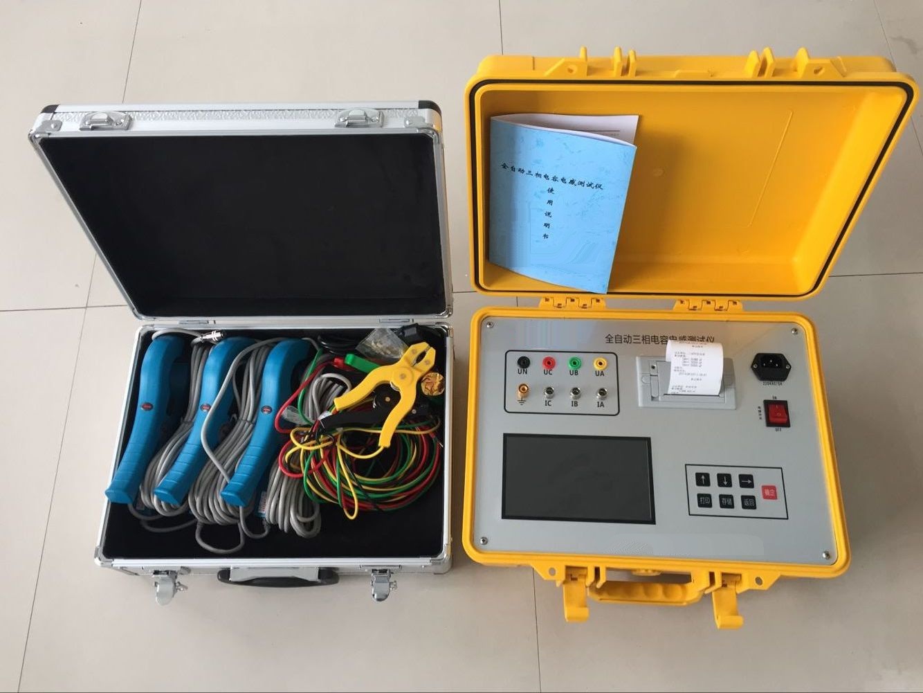
Aliases of Transformer Ratio Automatic Tester
Transformer ratio group tester, three-phase ratio tester, intelligent ratio tester, transformer three-phase ratio tester, intelligent ratio and impedance tester.
English
Technical characteristics of Transformer ratio automatic testing instrument
1. Fully automatic ratio measurement, no parameter setting required to automatically complete three-phase ratio and group tests.
2. Uses precision electronic components, ensuring long-term stable and reliable measurement accuracy.
3. Can measure transformers with connection groups such as Y/y, Y/d, D/y, D/d, Zn/y, Zn/d.
4. Can measure three-phase transformer groups and single-phase transformer polarity.
5. The total number of tap positions can be set arbitrarily; the instrument automatically calculates and stores data based on tap positions. No need for repeated input or manual calculation.
6. Accurate measurement and fast speed; continuous three-phase ratio measurement takes only a few seconds.
7. Can store or print all measurement results; the instrument has a built-in non-volatile memory that can save measurement data for long-term and can be reviewed at any time.
8. All Chinese menu and operation prompts, intuitive and convenient.
9. Non-volatile calendar and clock functions.
10. Dedicated computer input keyboard, with 100,000 fault-free operations.
11. The shell is sealed with professional engineering plastic, waterproof, moisture-proof, and shock-resistant.
Main Functions and Features
1. Automatically measure wiring group. 2. Automatically perform group transformation. 3. Automatically switch phase sequence. 4. Automatically switch range. 5. Automatically calibrate the meter. 6. After inputting the standard ratio, it can automatically calculate the relative error. 7. After one measurement is completed, the test voltage is automatically cut off. 8. Set data, measurement results are automatically saved, and previous data can be viewed. 9. For measuring on-load transformers, only input the ratio once. 10. Equipped with serial R232 interface. 11. Equipped with a micro printer, can also directly print out data results.
Main Technical Indicators
1. Ratio measurement range: 1—10000 2. Group: 1—12 points 3. Accuracy: 1-1000 0.2 class, 1000-10000 0.5 class 4. Power supply: AC220V ±10%, 50HZ 5. Operating ambient temperature: -5℃ ─ 40℃ 6. Operating ambient humidity: <85% 7. Volume: 430×320×215mm3 8. Weight: 8Kg
Operation Method
1. Wiring: Turn off the power switch of the instrument, and connect wires according to the following method. Single-phase transformer Three-phase transformer Instrument Transformer Instrument Transformer A A A A B X B B C Not connected C C a a a a b x b b c Not connected c c The neutral point of the transformer is not connected to the instrument or the ground. Connect the instrument ground wire properly. Insert one end of the power cord into the power socket on the instrument panel, and connect the other end to AC 220V power supply. Note: Do not reverse the high and low voltage connections of the transformer! Set wiring method Set standard ratio Start data measurement View historical data ↑: Select Confirm: Execute 2. Turn on the power switch of the instrument, and after a moment the main menu appears on the LCD screen, as shown below. The selected menu is displayed in reverse (black background with white text). At this time, press the "↑" key to select the function menu, and press the "Confirm" key to execute the corresponding function. Note: Press and release the key for one key input. Set wiring method Wiring: Yy Set standard ratio Start data measurement View historical data ↑: Select Confirm: Save 3. Wiring method setting: After entering the wiring method setting, the LCD screen displays as follows. At this time, press the "↑" key to select the wiring method, and press the "Confirm" key to save the wiring method and return to the main menu. Set wiring method Set standard ratio Ratio=25.000 Start measurement data View historical data →: Shift ↑↓: Increase/Decrease Confirm: Save 4. Set standard ratio: After entering the standard ratio setting, the LCD screen displays as follows. At this time, press the "→" key to select the data digit, and the selected digit is displayed in reverse. Press the "↑" and "↓" keys to modify the data. After selecting a digit, press the "↑" and "↓" keys, and the digit cycles from 0 to 9. If it is the first digit, it can only cycle from 1 to 9, and 0 will not appear. After selecting the decimal point, press the "↑" and "↓" keys to move the decimal point cyclically. Set wiring method Set standard ratio Tap ratio=0.00% Start measurement data View historical data →: Shift ↑↓: Increase/Decrease Confirm: Save If the transformer has taps, the standard ratio set here is the standard ratio of the middle tap. After pressing the "Confirm" key to save the ratio, the LCD screen displays as follows. The setting method for the tap ratio is the same as that for the standard ratio. If the transformer has taps, set according to the actual value; otherwise, set to 0.00%. After pressing the "Confirm" key to save the tap ratio, return to the main menu. 5. After preheating for 5 minutes, select "Start data measurement" and press the "Confirm" key, then display as follows. Wiring=Yy? Ratio=25.000? →: No Confirm: Yes ↑↓: Change tap The ratio value displayed on the screen is the actual standard ratio value needed for this measurement. Press the "↑" and "↓" keys to modify this value. The amplitude of each modification = set standard ratio × tap ratio. After the measurement is completed, display as follows. 3rd time Total 3 times Group: 12 points AB: 25.008 0.03% BC: 25.010 0.04% CA: 25.000 0.00% ↑: Page up →: Print Confirm: Return After each measurement, the instrument automatically saves the data, up to 30 data sets. After exceeding 30, the current data is stored in the 30th position, and the first data is cleared, i.e., first in, first out. The left side of the first line displays the position of this data in the historical data, and the right side displays the number of historical data. The second line is the group. The third line left is the ratio of AB phase, the third line right is the relative error of AB phase, and so on. If measuring a single-phase transformer, only the first three lines are displayed. If the relative error of the measured ratio is greater than 10%, display ">>10%"; if the relative error is less than -10%, display "<-10%". Press the "↑" key to view data. Press the "←" key to enter the print menu, can print this data, print all data, and can clear all historical data. Press the Confirm key to return to the main menu.
Precautions
1. During the measurement process, do not touch the test object.
2. If the test leads are short-circuited or the high and low voltage wires are reversed, the fuse will blow. After the fuse blows, if a measurement is attempted, it will stop after displaying "Measuring, please wait!". Please turn off the power, replace the fuse with the same capacity, and then re-measure.
3. The test leads must have good contact. The instrument should be properly grounded!
4. The working place of the instrument should be far away from strong electric fields, strong magnetic fields, and main frequency equipment. The power supply interference should be as small as possible; it is advisable to use lighting lines. If the power supply interference is still large, an AC purified power supply can be used to power the instrument. The capacity of the AC purified power supply should be greater than 200VA.
5. If the LCD screen display is disordered during operation, and all keys do not respond, or the measured value is far from the actual value, press the reset key, or turn off the power and then re-operate.
6. If the display has no character display or the color is too light, adjust the brightness potentiometer to a suitable value.
7. When working in dark places, the backlight can be turned on. To reduce the power consumption of the display, the backlight is not very bright.
8. The instrument should be stored in a dry and ventilated place.