


LYYD-75KVA/150KV Portable High-Voltage Test Transformer Product Overview
It is a new type of product produced after improvements based on the same type of YDJ (G) transformer, in accordance with the national standard for transformers ZBK41006—89. This series of products features small size, light weight, compact structure, complete functions, and ease of use. It is suitable for power, industrial and mining, scientific research and other departments, for power frequency withstand voltage tests and DC leakage tests on various high-voltage electrical equipment, electrical components, and insulating materials. It is an indispensable instrument in high-voltage testing.
II. LYYD-75KVA/150KV Portable High-Voltage Test Transformer Product Structure
The iron core is of single-frame type. The coil adopts a concentric cylindrical multi-layer tower structure. The primary low-voltage winding is wound on the iron core, and the secondary high-voltage winding is wound on the outside of the low-voltage winding. This coaxial arrangement reduces the coupling loss between windings. The high-voltage silicon stack is encapsulated in the bushing with a special process. The product shell is made into an octagonal structure that fits well with the core, and the overall appearance is beautiful and generous. Its internal and external structure is shown in Figure 1.
Product Model Meaning
Y D Q C( )—□ / □
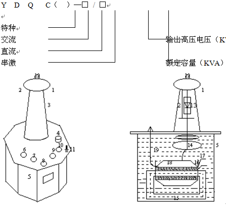
Figure 1: Structural Schematic Diagram
1-Equalizing ball; 2-Silicon stack short-circuit rod; 3-High-voltage bushing; 4-Oil valve; 5-Housing; 6,7-Voltage adjustment input terminals a, x; 8,9-Instrument measurement terminals E, F; 10-High-voltage tail terminal X; 11-Transformer housing grounding terminal; 12-High-voltage output terminal A; 13-High-voltage rectifier silicon stack; 14-Internal equalizing ring; 15-Transformer iron core; 16-Primary low-voltage winding; 17-Instrument measurement winding; 18-Secondary high-voltage winding; 19-Transformer oil.
LYYD-75KVA/150KV Portable High-Voltage Test Transformer Working Principle
It is a single-phase transformer with connection group label II. The working process of a single transformer: AC 220V (380V for above 10KVA) is connected to the power control box (cabinet), and the voltage is adjusted to 0~200V (0~400V for above 10KVA) by the auto-transformer (external for above 50KVA) inside the power control box (cabinet) to the primary winding of the test transformer. According to the principle of electromagnetic induction, the required high voltage for testing can be obtained in the high-voltage winding of the transformer. Its working principle diagram is shown in Figure 2.
1. Working Principle Schematic Diagram
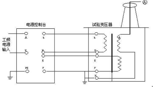
Figure 2: Working Principle Schematic Diagram
In the test transformer: a, x are low-voltage input terminals; A, X are high-voltage output terminals; E, F are instrument measurement terminals.
2. The working principle of a single AC/DC dual-purpose transformer is shown in Figure 3. In the figure: a high-voltage silicon stack is installed inside the high-voltage bushing, connected in series in the high-voltage circuit for high-voltage rectification to obtain DC high voltage. When a short-circuit rod is used to short-circuit the high-voltage silicon stack, AC high voltage can be obtained, and its state is AC output; conversely, when the short-circuit rod is pulled out, its state is DC output.
3. The principle of obtaining higher voltage by cascading three transformers is shown in Figure 4. Cascaded transformers have great advantages because the entire test device is composed of multiple single cascaded transformers. A single test transformer has the characteristics of small size, light weight, and easy transportation. It can be used in series to combine outputs several times higher than a single test transformer, or it can be used separately. The entire test device has low investment and is economical. As shown in Figure 3: In the cascaded use of three cascaded test transformers, the output voltage of each single transformer B1, B2, B3 is U. The first and second stage test transformers each have an excitation winding, namely A1, C1 and A2, C2. When the control voltage is applied to the primary winding a1, x1 of the first-stage transformer B1, the excitation winding A1, C1 supplies power to the primary winding of the second test transformer B2, and the excitation winding A2, C2 of the second-stage test transformer B2 supplies power to the primary winding of the third test transformer B3. Since the high-voltage tail and housing of the first-stage transformer B1 are grounded, the second and third-stage transformers B2 and B3 are isolated from the ground by insulating supports, so the output voltages of transformers B1, B2, B3 to ground are 1U, 2U, 3U respectively.
