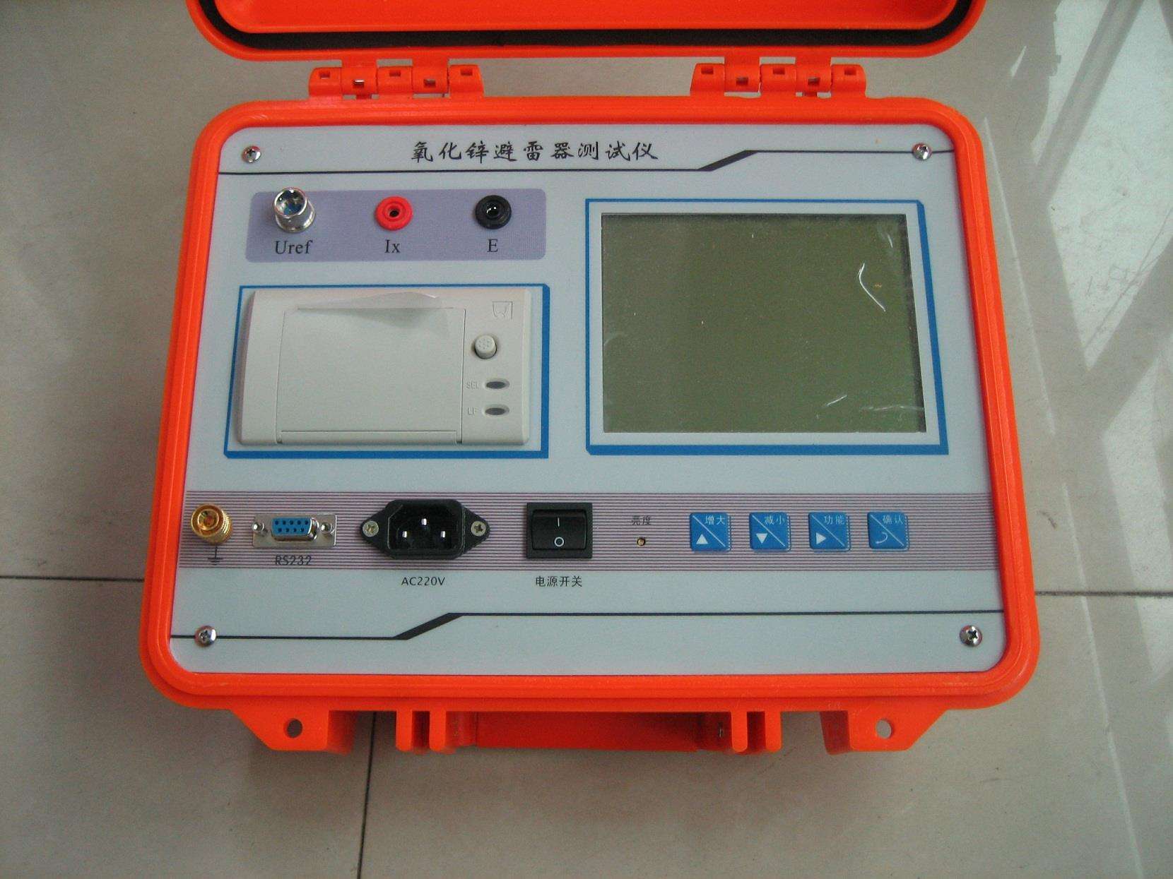
It complies with the requirements of the People's Republic of China electric power industry standard "DL474.5—92 Guidelines for On-site Insulation Tests — Arrester Tests". This instrument uses advanced technologies such as microcomputer sampling and control. It can measure the total current, third harmonic, resistive current, resistive current peak, capacitive current, active power, etc. of zinc oxide arresters under power frequency voltage. It also displays voltage and current waveforms and prints output. It adopts a large-screen LCD display with Chinese menu prompts for operation, enhancing human-machine interaction. It also provides on-site wiring display. This instrument features simple wiring, high measurement accuracy, and strong reliability.
Indicators
1. Measurement parameters and range test voltage: KV
Zinc Oxide Arrester Resistive Current Live Tester
Third harmonic voltage: KV
Total current (peak): 0-20 mA
Third harmonic current: 0-20 mA
Resistive current (peak): 0-20 mA
Resistive current peak: 0-20 mA
Capacitive current (peak): 0-20 mA
Arrester power consumption: 0-8W
In addition to displaying the above measured values, it can also display voltage and total current waveforms.
2. Measurement error:
Test voltage: ±2%
Total current: ±2%
Resistive current: ±5%
Capacitive current: ±5%
Arrester power consumption: ±5%
3. Input signals:
Voltage signal (PT low-voltage side): AC 5 ~ 200V
Current signal: AC 0 ~ 20mA
4. Working power supply:
AC 220V±10% 50Hz
5. Battery continuous working time: more than 8 hours
6. Battery charging time: more than 6 hours
7. Instrument dimensions: 34cm×22cm×20cm
8. Instrument weight: 5kg (excluding cable box)
Modes
1. Wired Mode:
The instrument inputs the PT secondary voltage as a reference signal, and simultaneously inputs the MOA current signal. After Fourier transform, the voltage fundamental U1, current fundamental peak Ix1p, and current-voltage angle Φ can be obtained. Therefore, the component in phase with the voltage is the resistive current fundamental peak (Ir1p), and the orthogonal component is the capacitive current fundamental peak (Ic1p):
Ir1p=Ix1pCOSΦ Ic1p=Ix1pSINΦ
Considering that δ=90°—Φ is equivalent to the dielectric loss angle, it is also very simple to evaluate MOA directly using Φ: when there is no "inter-phase interference", Φ is mostly between 81°~86°. According to the requirement that "resistive current should not exceed 25% of total current", Φ should not be less than 75.5°. Refer to the table below for segmented evaluation of MOA performance:
| Performance | <75° | 75°~77° | 78°~80° | 81°~83° | 84°~89° | >89° |
| Φ | Poor | Bad | Fair | Good | Excellent | Interference |
Actually, attention should be paid when Φ<80°.
Grounding:
Before measurement, connect the ground wire first, and disconnect the ground wire last after measurement! If there is paint or rust at the grounding point, it must be cleaned thoroughly.
Reference voltage
One end of the reference voltage signal line is inserted into the reference voltage socket, and the other end is connected to the PT secondary low-voltage output of the phase under test: the small black clip connects to the neutral point (x), and the small red clip connects to the phase voltage (a/b/c) under test. When using external application method, connect to the measuring winding of the step-up transformer. If the PT is far away, an extension line can be used. Near each of the two small clips, there is a 0.1A fuse to prevent accidental burning of the PT fuse. If the 0.1A fuse is damaged, replace it with a fuse of the same specification.
2. Induction Mode:
An electric field induction sensor is installed on the MOA base. Its induced current leads the electric field strength (bus voltage) by 90°. After integration, it is in phase with the electric field strength or bus voltage. Therefore, the signal from the electric field induction sensor can be used as a measurement reference. The instrument inputs the electric field induction sensor signal and simultaneously inputs the MOA current signal. After Fourier transform, the electric field fundamental E1, current fundamental peak Ix1p, and current-electric field angle Φ can be obtained. The component in phase with the electric field is the resistive current fundamental peak (Ir1p), and the orthogonal component is the capacitive current fundamental peak (Ic1p).
Using B-phase induction signal as reference
Because the influence of the electric fields of the A/C side phases on the B-phase base cancels out, the induction plate should be placed on the B-phase MOA base at a position symmetrical to the A/C phases to obtain correct phase information for the B phase. The electric fields of the A/C phase MOA bases are affected by the B phase; do not place the induction plate on the A/C phase MOA bases.