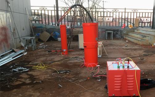
Before actual operation, we need to make some preparations, such as gaining a theoretical understanding of the series resonance device. This helps us assemble and use the equipment. We need to understand how to connect the wires, how to assemble the equipment, and why we do it this way. Next, let's first understand the principle of the variable frequency series resonance withstand voltage device.
First, let's start with the assembly of the variable frequency series resonance withstand voltage device. We all know that series resonance consists of four basic instruments: variable frequency power supply, excitation transformer, reactor, and voltage divider (some with compensation capacitors). So why is there an additional compensation capacitor? How to connect the compensation capacitor?
Let's take an experiment as an example. The test sample is a cable with a length of about 15 meters, a single-core cross-section of 70 millimeters, and a voltage level of 8.7/10 kV.
We know the length of the cable, the cross-sectional area of the single core, and the voltage level. Then, through the cable capacitance calculator, we get a cable capacitance value of 0.0033uf. We can also obtain the resonance frequency and current value. By checking the national standard, we can determine that the test withstand voltage is 17.5kV. What is the use of knowing these? First, we need to know what series resonance is.
In a series circuit composed of resistance, inductance, and capacitance, when the capacitive reactance xc equals the inductive reactance xl, that is, xc=xl, the voltage u and current i in the circuit are in phase, and the circuit presents pure resistance, which is called series resonance.
The series resonance frequency can only work directly between 30 and 300, and it is effective only when it does not exceed 300.
Many power users directly use 0.0033uf as the capacitance value to calculate the frequency value, which may be wrong. The nameplate on the voltage divider indicates a capacitance value of 2500pf. So we need to add 2500pf. That's not enough. We need to know the capacitance and inductance values.
Here, the inductance of the reactor nameplate is 60h, and the current is 1.25A, so that the frequency and current values can be calculated. For the test cable, one reactor can be completed.
Start wiring, instrument and cable wiring
Connect the variable frequency power supply to the 380V power supply, connect the power output line to the excitation transformer, and connect the excitation transformer and switch the card according to the excitation transformer screen diagram. The grounded variable voltage output line is used to connect the reactor. The reactor is connected to the divider. There are two divider data lines. Here, only one line (the other is a spare) is used to connect to the variable frequency power supply. Then ground the grounding terminals of the variable frequency power supply, excitation transformer, and voltage divider respectively. Many electricians will forget that the X terminal of the excitation transformer also needs to be grounded. This is a special reminder for electricians trained on site. Can the compensation capacitor be used for field tests? How to connect the compensation capacitor to calculate the frequency requires adding the compensation capacitance value, otherwise it cannot. When adding the compensation capacitor, the compensation capacitor is directly connected in parallel to the voltage divider, and the grounding terminal can be grounded. The compensation capacitor needs to be connected when used as the main transformer, because the capacitance value of the main transformer is very small, so we connect the compensation capacitor when it is used as the main transformer.
Instrument assembly connection
The wires between the reactor and the voltage divider are directly connected to the phase of the cable to be tested. The other two phases and the shielding wire of the cable are grounded, and the other end of the cable is separated by trees. Note: Before connecting the cable, an insulation test should be performed on the cable to confirm that the insulation between each phase and ground, and between phases, is intact. After wiring is completed, turn on the power and set the variable frequency power supply. There are two main places to modify: one is the test voltage, and the other is the withstand voltage time. After setting, the first test is automatic test, and the second test is manual test.
Manual test: You can manually adjust the frequency to find the resonance point, manually raise it to the required voltage, click start time, complete the time, and click step-down stop.
Automatic test: Directly enter the automatic test interface, click automatic test, and the test will automatically find the resonance point, boost voltage, time, and step down.
There are two operation modes (manual and automatic)
During operation, various problems may inevitably occur. Before operation, be sure to read the equipment manual in detail and consult professionals.