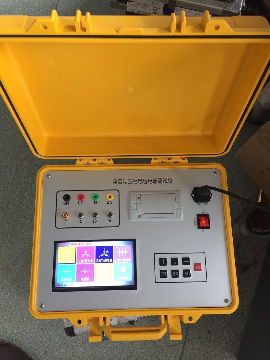
Transformer Tester / Inductance Tester Parameters Automatic Capacitance Bridge / Inductance Tester Parameters
Product Application:
It is specially developed under the guidance of the expert working group for reactive power compensation devices, aiming at the problems existing in on-site measurement of the capacitance of individual capacitors in shunt capacitor banks at substations. It mainly solves the following problems:
(1) On-site measurement of individual capacitors requires disconnecting connecting wires, which not only involves heavy workload but also easily damages the capacitors;
(2) The low output voltage of capacitance meters leads to a low fault detection rate.
(3) Measuring the inductance of reactors. This instrument features small measurement workload, quick and simple operation, stable performance, accurate measurement, and high fault detection rate.
In addition, its current measurement unit can also be used for measuring electrical equipment such as CVTs and arresters, providing multi-functionality in one instrument.
Technical Parameters:
1. Capacitance range: 0.2μF~2,000μF;
Capacity range: 5~20,000 kvar;
Measurement accuracy: ±1.5%×reading±2 digits;
Resolution: ±1.0%rdg;
2. Inductance range: 1mH~9.99H; Measurement accuracy: ±1.5%±2 digits
3. Output measurement voltage: AC 26V/500VA; 50Hz;
4. Display mode: Large-screen LCD with full Chinese output, TPμp-40 panel-mounted thermal printer
5. Dimensions and weight: 370×370×220 mm / 8 kg
6. Working conditions:
Ambient temperature: 0℃ ~ +40℃, Relative humidity: ≤90%
Power supply: AC 220V±10%; 50Hz;
Measurement range, resolution, and error values
|
Capacitance measurement range: |
Error value: |
|
0.020μF ~ 0.200μF |
±0.5% |
|
0.200μF ~ 2.000μF |
±0.5% |
|
2.000μF ~ 20.00μF |
±0.5% |
|
20.00μF ~ 200.0μF |
±0.5% |
|
200.0μF ~ 2000.μF |
±0.5% |
|
Capacitor reactive power |
0 ~ 20.00Mvar |
Error value |
±1% |
|
Capacitor active power |
0 ~ 20.00kW |
Error value |
±1% |
|
Capacitor dissipation factor |
0 ~ 20.00% |
Error value |
±1% |
|
Capacitor resistance component |
0 ~ 10.00MΩ |
Error value |
±1% |
|
Inductance measurement range |
Error value |
|
0.10mH ~ 0.200H |
±0.5% |
|
2.000H ~ 20.00H |
±0.5% |
|
20.00H ~ 200.0H |
±0.5% |
|
200.0H ~ 2000.H |
±0.5% |
|
Inductor reactive power |
0 ~ 20.00Mvar |
Error value |
±1% |
|
Inductor active power |
0 ~ 20.00kW |
Error value |
±1% |
|
Inductor dissipation factor |
0 ~ 20.00% |
Error value |
±1% |
|
Inductor resistance component |
0 ~ 10.00MΩ |
Error value |
±1% |
Clamp sensor measurement range and error (component)
|
Current measurement range (AC) |
Error value |
|
0.000mA ~ 50.00A |
±0.2%
|
Product Features:
(1) Automatic range conversion;
(2) Storage of 2000 test data;
(3) Large-screen LCD (320×240 LCD) display, Chinese menu operation prompts;
(4) Simultaneous display of waveform and measurement processing data on the same screen, making the test process more intuitive;
(5) With setting, calibration, and debugging functions.
It features small measurement workload, quick and simple operation, stable performance, accurate measurement, and high fault detection rate; it can also measure the inductance of reactors, discharge resistance measurement function, measure the current and capacitance of coupling capacitors under live conditions, calculate the capacity of the measured capacitance; simultaneously display voltage and current waveforms and phase; automatic range conversion, data storage; large-screen LCD display, Chinese output, and printing capability.
Working Principle:
Due to the adoption of synchronous sampling technology for standard capacitors and capacitors under test, it is not affected by power supply voltage fluctuations; moreover, the measurement process is fully automatic, avoiding errors caused by manual operation, thus featuring good stability, repeatability, accuracy, and reliability.